Electrical connector

Active Publication Date: 2017-05-16
CHENG UEI PRECISION IND CO LTD
View PDF1 Cites 17 Cited by
  • Summary
  • Abstract
  • Description
  • Claims
  • Application Information

AI Technical Summary

Benefits of technology

[0006]An object of the present invention is to provide an electrical connector capable of improving the high frequency performance thereof. The electrical connector includes an insulating assembly, terminals, an inner shielding assembly and an outer shielding assembly. The insulating assembly has a tongue board at a front thereof, a rear of a top side of the tongue board protrudes upward to form upper support bumps, a rear of a bottom side of the tongue board protrudes downward to form lower support bumps. The terminals are insert molded the insulating assembly and are divided into an upper row and a lower row. The terminals have contact portions located at the top side and the bottom side of the tongue board, fixed portions fixed in the insulating assembly and solder portions exposed from the insulating assembly, outmost two of the upper row of terminals and outmost two of the lower row of terminals are grounding terminals, outsides of rears of the contact portions of the grounding terminals form touch portions. The inner shielding assembly includes an upper shielding piece and a lower shielding piece, the upper shielding piece has an upper base plate and

Problems solved by technology

However, the high frequency impedance of the terminals of the electrical connector can not meet a nor

Method used


Image

  • Electrical connector
  • Electrical connector
  • Electrical connector

Examples


Example

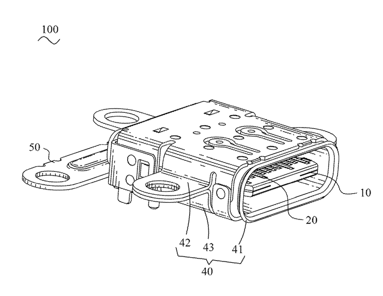
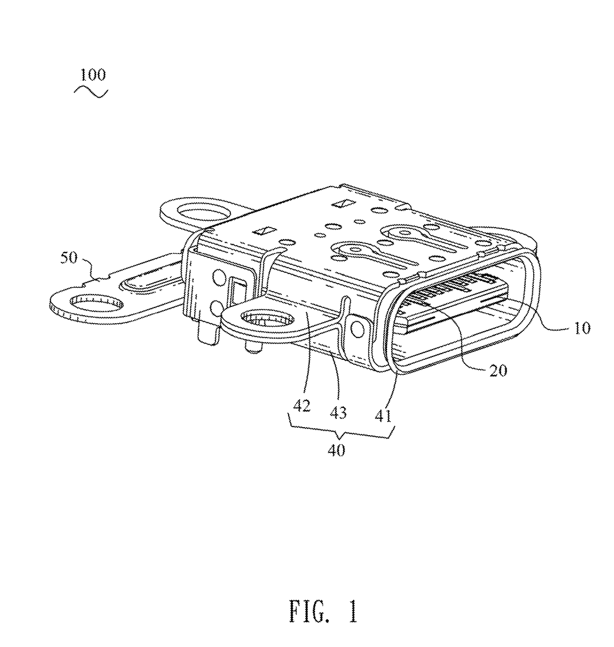
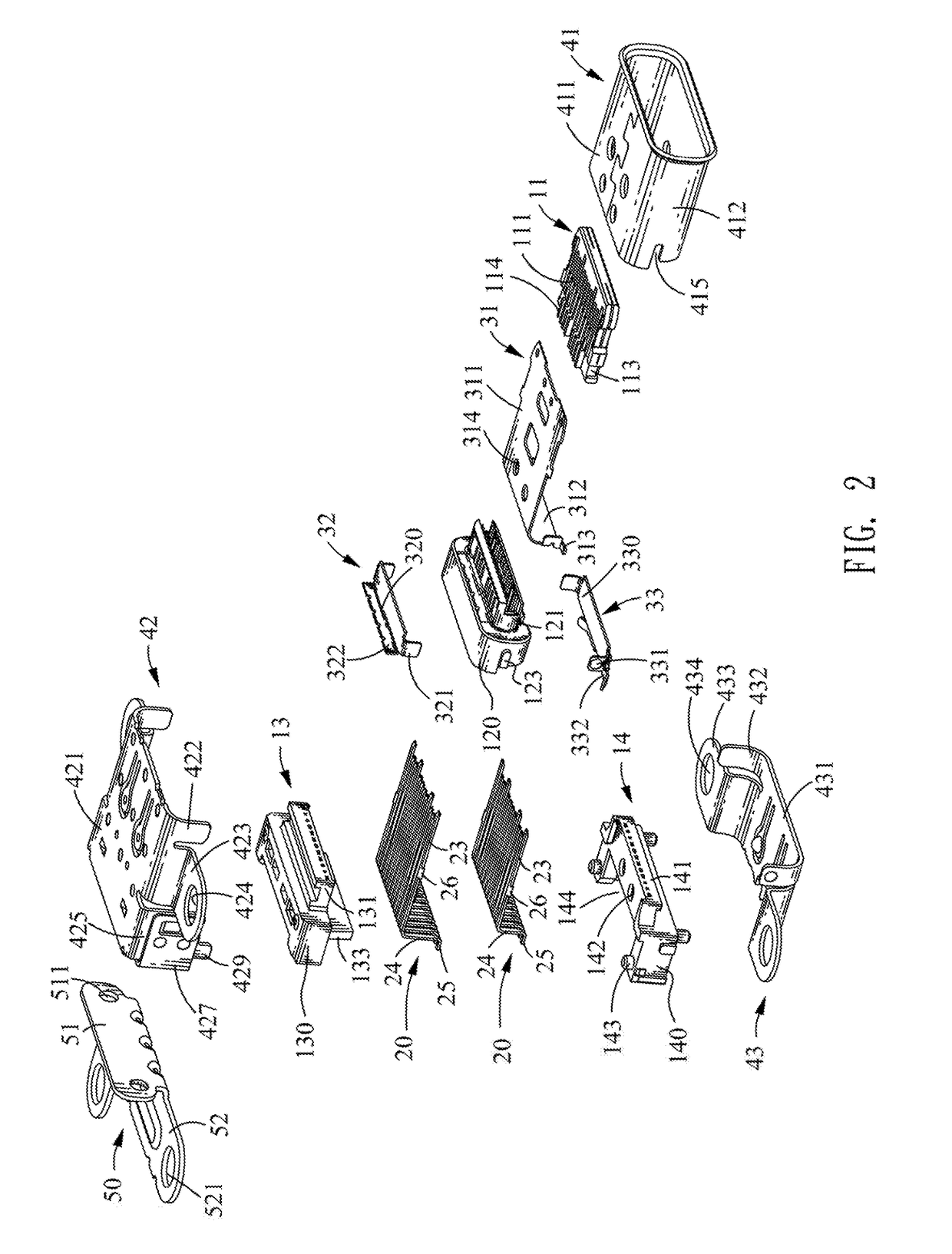
[0021]With reference to FIGS. 1-3, an electrical connector 100 in accordance with an embodiment of the present invention is shown. The electrical connector 100 is mounted to a circuit board (not shown) and includes an insulating assembly 10, an inner shielding assembly 30, terminals 20, an outer shielding assembly 40 and a mounting frame 50.

[0022]Referring to FIG. 2 and FIG. 3, the insulating assembly 10 includes a separate tongue board 11, an insulating body 12, an upper dielectric body 13 and lower dielectric body 14.

[0023]The separate tongue board 11 defines a plurality of first terminal grooves 111 at a top surface thereof and a plurality of second terminal grooves 112 at a bottom surface thereof. A rear of each of two side surfaces of the separate tongue board 11 defines a fixing groove 113 penetrating a top and a bottom thereof. A rear portion of each of outmost two of the first terminal grooves 111 penetrates outward one of the two side surfaces of the separate tongue board 1...


PUM


Abstract

An electrical connector includes an insulating assembly, terminals, an inner shielding assembly and an outer shielding assembly. The insulating assembly has a tongue board at a front. The terminals are insert molded the insulating assembly and are divided into an upper row and a lower row with contacts portions located at a top side and a bottom side of the tongue board. Outmost two of the upper row of terminals and outmost two of the lower row of terminals are grounding terminals, outsides of rears of the contact portions of the grounding terminals form touch portions. The inner shielding assembly includes an upper shielding piece and a lower shielding piece located to a rear of the tongue board. The outer shielding assembly includes a shielding sleeve sleeving and spaced from the tongue board, the shielding sleeve contacts with at least one of the upper shielding piece and the lower shielding piece.

Description

BACKGROUND OF THE INVENTION[0001]1. Field of the Invention[0002]The present invention generally relates to an electrical connector, and more particularly to an electrical connector capable of improving anti-abrasion performance.[0003]2. The Related Art[0004]A traditional electrical connector includes an insulating housing, a middle shielding plate, terminals and a shielding shell. The middle shielding plate is insert-molded in the insulating housing. The terminals are divided into two rows received in an upper side and a lower side of the insulating housing, respectively. The middle shielding plate is located between the two rows of terminals. Each of the terminals has a fixed portion, a contact portion extended frontward from a front end of the fixed portion and a solder portion extended from a rear end of the fixing portion. The shielding shell is mounted outside the insulating housing. An inserting space is formed between a front end of the shielding shell and a front end of the ...

Claims


Application Information

Patent Timeline
IPC IPC(8): H01R13/648H01R13/6585H01R13/405H01R24/60H01R107/00
CPCH01R13/6585H01R13/405H01R24/60H01R2107/00
Inventor SU, YU-HUNGWANG, CHIN-CHOU
Owner CHENG UEI PRECISION IND CO LTD
Why Eureka
Try Eureka