Electrical connector

a technology of electrical connectors and connectors, applied in the direction of coupling device connections, coupling protective earth/shielding arrangements, two-part coupling devices, etc., can solve the problem of lowering the defect rate of shielding plates, and achieve the effect of reducing high-frequency noise, simple and shorter structure, and simple shielding pla

Active Publication Date: 2017-05-16
CHENG UEI PRECISION IND CO LTD
View PDF12 Cites 23 Cited by
  • Summary
  • Abstract
  • Description
  • Claims
  • Application Information

AI Technical Summary

Benefits of technology

[0011]As described above, the touch portion of the ground element contacts the shielding plate to make the shielding plate realize a ground function, so the shielding plate has a simpler and shorter structure, and a mold for making the shielding plate is simpler and litter. Furthermore, a distance between the front plate of the grounding conductor and the first bent portions of the first terminals is substantially equal to a distance between the rear plate of the grounding conductor and the second bent portions of the second terminals for resisting high-frequency noises, so the high-frequency noises are decreased. As a result, a process problem of making the shielding plate is improved, and a defect rate of the shielding plate is lowered.

Problems solved by technology

As a result, a process problem of making the shielding plate is improved, and a defect rate of the shielding plate is lowered.

Method used


Image

  • Electrical connector
  • Electrical connector
  • Electrical connector

Examples


Embodiment Construction

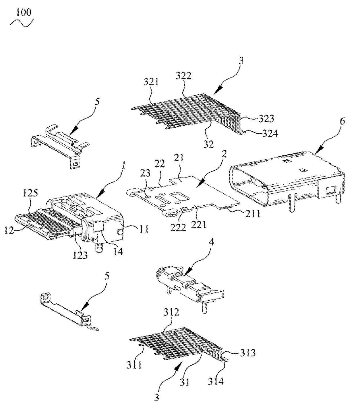
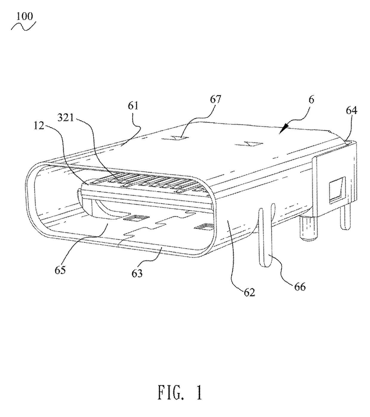
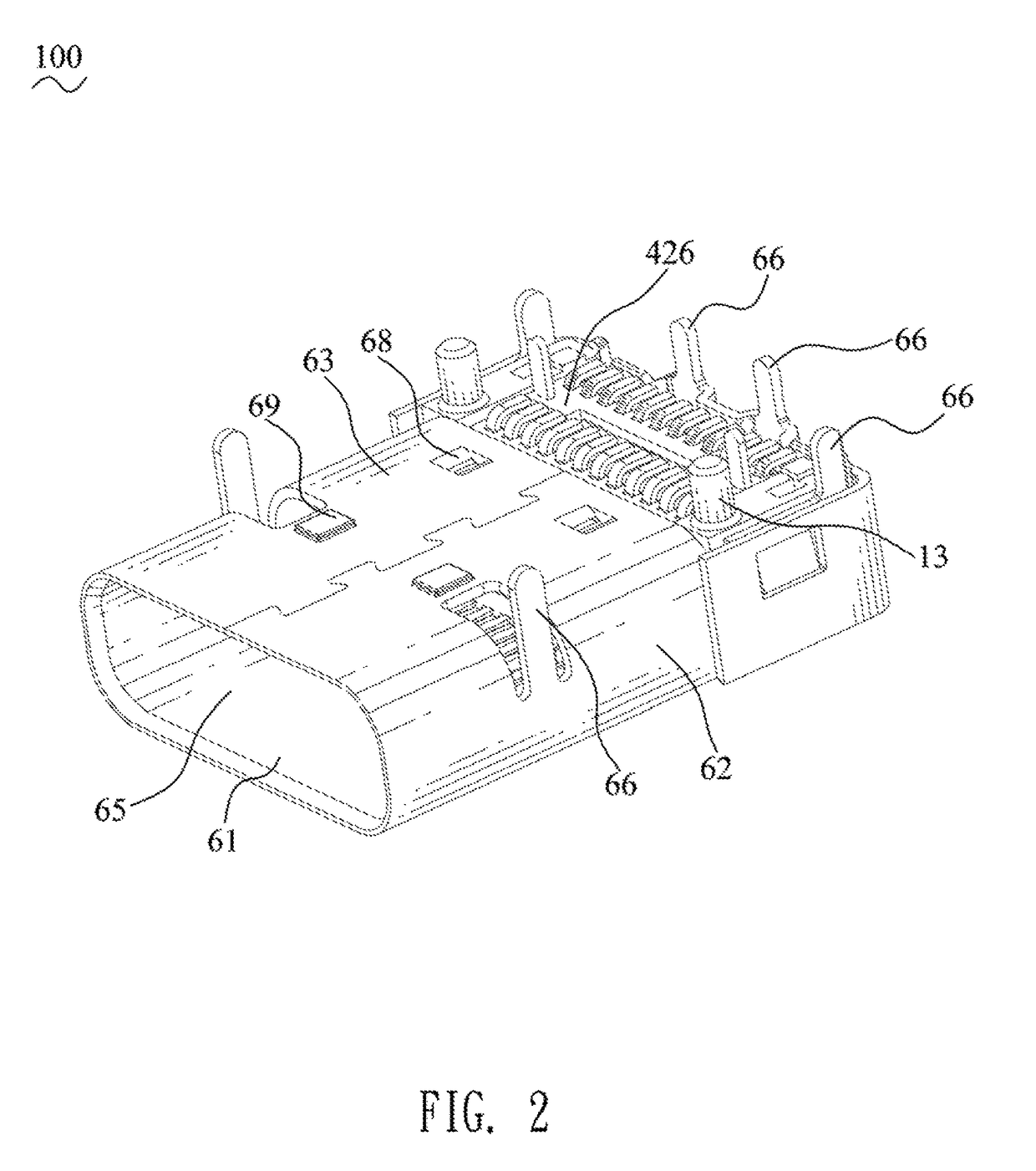
[0027]With reference to FIG. 1 to FIG. 3, an electrical connector 100 in accordance with the present invention is shown. The electrical connector 100 mounted to a circuit board (not shown), includes an insulating housing 1, a shielding plate 2, a plurality of conductive terminals 3, a ground element 4, an inner shielding shell assembly 5 and an outer shielding shell 6. The shielding plate 2 is received in the insulating housing 1. The conductive terminals 3 are received in the insulating housing 1. The ground element 4 for being connected between the shielding plate 2 and ground is received in the insulating housing 1. The inner shielding shell assembly 5 is mounted on the insulating housing 1.

[0028]Referring to FIG. 1, FIG. 2, FIG. 3, FIG. 9, FIG. 10, FIG. 11 and FIG. 14, the insulating housing 1 is integrally molded by virtue of an injection way. The insulating housing 1 has a base portion 11, and a tongue portion 12 connected to a front surface of the base portion 11. The tongue ...


PUM


Abstract

An electrical connector includes an insulating housing, a plurality of conductive terminals, a shielding plate and a ground element. The insulating housing has a base portion, and a tongue portion protruded frontward from a front surface of the base portion. The conductive terminals are received in the insulating housing, and front ends of the conductive terminals are exposed to the tongue portion. The shielding plate is received in the insulating housing. The ground element is for being connected between the shielding plate and ground. The ground element is received in the insulating housing. The ground element has a touch portion contacting the shielding plate.

Description

BACKGROUND OF THE INVENTION[0001]1. Field of the Invention[0002]The present invention generally relates to an electrical connector, and more particularly to a USB Type-C electrical connector.[0003]2. The Related Art[0004]In order to unify electrical connectors of different equipments for improving universalities of the electrical connectors, USB (Universal Serial Bus) connectors are the most popular interfaces of current computers. The USB connectors support plug-and-play external buses. The USB connectors are used for connecting with multiple kinds of peripheral devices, including loudspeakers, telephones, game controllers, printers, tablet devices, cameras and so on. With the popularization of the USB connectors, except for data transmissions, the current USB connectors are widely used in a charging field.[0005]With the development of electronic industries, in order to make the USB connectors more popularly applied in various devices, and solve a drawback that a USB 2.0 connector ...

Claims


Application Information

Patent Timeline
Patent Type & Authority Patents(United States)
IPC IPC(8): H01R13/648H01R13/652H01R13/6594H01R24/60
CPCH01R13/6594H01R13/652H01R24/60H01R13/6583
Inventor YUAN, SHENG-TSUNGYU, SHENG-NAN
Owner CHENG UEI PRECISION IND CO LTD
Why Eureka
Try Eureka