Linear vibration motor

a linear vibration and motor technology, applied in mechanical vibration separation, dynamo-electric machines, electrical apparatus, etc., can solve the problems of increasing the number of generation of vibrations, increasing the operational life of the motor, and generating contact noise, so as to reduce the noise of metallic high frequency, increase the spatial utilization, and enhance the degree of design freedom of the linear vibration motor

Inactive Publication Date: 2012-07-05
MPLUS
View PDF6 Cites 12 Cited by
  • Summary
  • Abstract
  • Description
  • Claims
  • Application Information

AI Technical Summary

Benefits of technology

[0012]The present invention has been made in an effort to provide a linear vibration motor in which a damper is provided between an elastic member and a weight or between the elastic member and an inner surface of a casing, so that the damper can mitigate met...

Problems solved by technology

First, because the number of generation of vibrations is increased compared to that when incoming calls are received, the operational lifespan thereof must be increased.
In conventional linear vibration motors having the above-mentioned construction, the vibrator collides with a casing or a bracket when it vibrates, thus generating contact noise.
However, in the c...

Method used


Image

  • Linear vibration motor
  • Linear vibration motor
  • Linear vibration motor

Examples


first embodiment

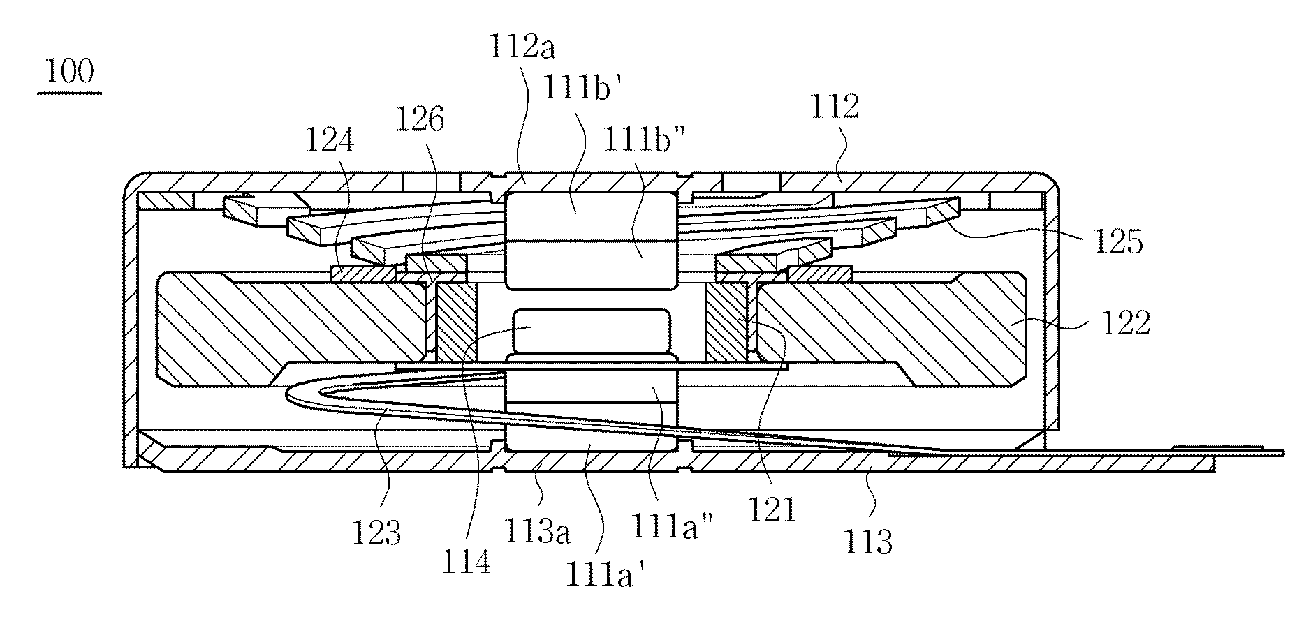
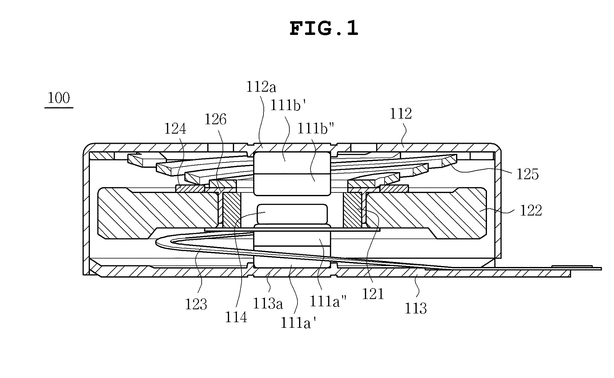
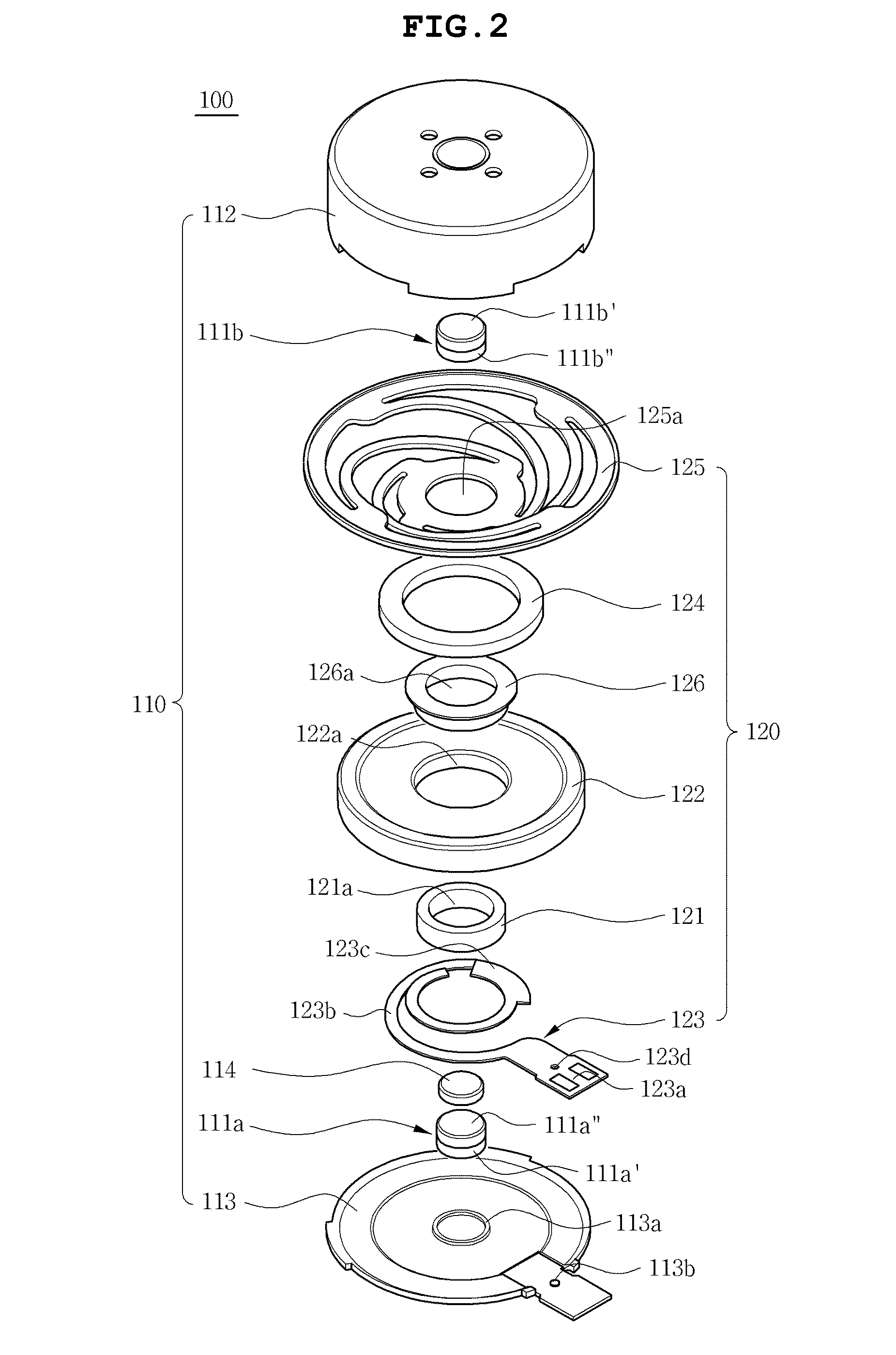
[0038]FIG. 1 is a sectional view showing a linear vibration motor 100, according to the present invention. FIG. 2 is an exploded perspective view of the linear vibration motor 100 of FIG. 1. As shown in the drawings, the linear vibration motor 100 includes a stator 110 and a vibrator 120. The stator 110 includes magnets 111a and 111b, a casing 112, a bracket 113 and a plate yoke 114. The vibrator 120 includes a coil 121, a weight 122, a PCB (printed circuit board) 123, a damper 124, an elastic member 125 and a cylindrical yoke 126.

[0039]In detail, the casing 112 of the stator 110 has an internal space to cover the vibrator 120. The casing 112 is coupled to the bracket 113. The PCB 123 is also fastened to the bracket 113. The magnets 111a and 111b comprise a first magnet 111a which is attached to an inner surface of the bracket 113 at a position facing the weight 122, and a second magnet 111b which is attached to an inner surface of an upper plate of the casing 112 at a position faci...

second embodiment

[0054]The damper 224 of the vibrator 220 is attached to a lower surface of an upper plate of the casing 212 at a position facing the elastic member 225. Thus, when the vibrator 220 vibrates, metallic high frequency noise attributable to friction between the elastic member 125 and the casing 212 can be mitigated. the present invention can also increase the spatial utilization, thus enhancing the degree of freedom in design of the motor.

[0055]In the second embodiment having the above-mentioned construction, when external power is supplied to the coil 221 through the PCB 223, the vibrator 220 linearly vibrates using electromagnetic force generated by the coil 221 and the magnets 211a and 211b. Even though the displacement of the vibrator 220 excessively increases, the damper 224 prevents the elastic member 225 from coming into direct contact with the casing 212, thus mitigating metallic high frequency noise attributable to friction between them. Furthermore, the spatial utilization is ...

third embodiment

[0057]FIG. 4 is a sectional view showing a linear vibration motor 300, according to the present invention. As shown in the drawing, the linear vibration motor 300 includes a stator 310 and a vibrator 320. The stator 310 includes a coil 311, a PCB 312, a bracket 313 and a casing 314. The PCB 312 is connected to the coil 311 and fastened to the bracket 313. The casing 314 has an internal space to cover the vibrator 320 and is coupled to the bracket 313.

[0058]The vibrator 320 includes a magnet 321, a yoke 323, a weight 322, an elastic member 325 and a damper 324. The magnet 321 is disposed facing the coil 311. The yoke 323 is coupled to the magnet 321. The weight 322 is fitted over a circumferential outer surface of the yoke 323. A first end of the elastic member 325 is coupled to the stator 310 while a second end thereof is coupled to the yoke 323. The damper 324 is provided on the upper surface of the weight 322 that faces the elastic member 325.

[0059]In the third embodiment having t...


PUM


Abstract

Disclosed herein is a linear vibration motor. The motor includes a stator and a vibrator. The stator includes a magnet. The vibrator includes a coil facing the magnet. A weight is coupled to the coil. A PCB is connected to the coil and the stator. An elastic member is coupled to stator and the coil. A damper is provided on the weight at a position facing the elastic member. The damper may be provided between the elastic member and the weight or between the elastic member and the inner surface of a casing. The damper can mitigate metallic high frequency noise attributable to friction between the elastic member and the weight or between the elastic member and the casing. Furthermore, the spatial utilization is increased, thereby enhancing the degree of freedom in designing the linear vibration motor.

Description

CROSS REFERENCE TO RELATED APPLICATION[0001]This application claims the benefit of Korean Patent Application No. 10-2010-0138945, filed Dec. 30, 2010, entitled “Linear vibration motor,” which is hereby incorporated by reference in its entirety into this application.BACKGROUND OF THE INVENTION[0002]1. Technical Field[0003]The present invention relates to a linear vibration motor.[0004]2. Description of the Related Art[0005]Generally, vibration motors convert electric energy into mechanical energy using the principle of generation of electromagnetic force. Such vibration motors are installed in electronic devices, such as mobile communication terminals, portable terminals, etc., and are used to indicate signal reception in a mute mode.[0006]Furthermore, in accordance with the rapid growth of wireless communication and mobile phone markets, a variety of multifunctional mobile communication terminals have recently gained popularity. This trend requires high quality compact mobile commun...

Claims


Application Information

Patent Timeline
IPC IPC(8): H02K33/18
CPCB06B1/045H02K33/18
Inventor YOON, AN SOOOH, HWA YOUNGCHOI, JOONLEE, KWANG HYUNGCHOI, JUN KUN
Owner MPLUS
Why Eureka
Try Eureka