DC power supply

A DC power supply and circuit technology, applied in the direction of output power conversion devices, electrical components, DC power input conversion to DC power output, etc., can solve problems such as damage, exceeding diode withstand voltage, and impact

Active Publication Date: 2012-09-05
HITACHI LTD
View PDF9 Cites 11 Cited by
  • Summary
  • Abstract
  • Description
  • Claims
  • Application Information

AI Technical Summary

Problems solved by technology

The recovery characteristics are determined by the properties of the diode, such as Figure 9 Exceeding the withstand voltage of the diode as shown, in many cases leads to destruction
In addition, even if the

Method used


Image

  • DC power supply
  • DC power supply
  • DC power supply

Examples


Embodiment 1

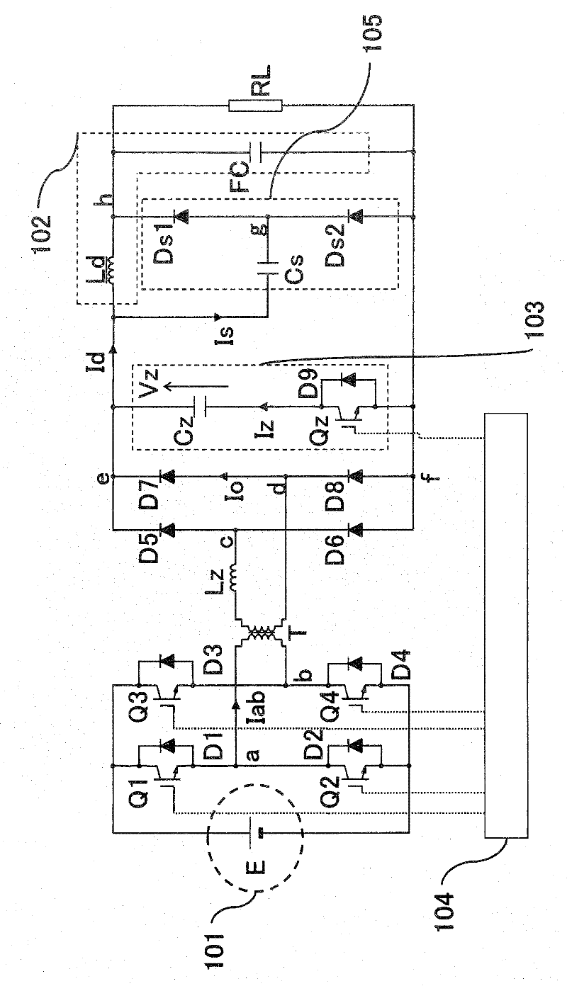
[0127] Hereinafter, as Embodiment 1 of the present invention, according to figure 1 Describe its composition. 101 is an input DC power supply, 102 is a filter circuit composed of a filter reactor Ld and a filter capacitor FC, 103 is a resonant switch circuit, 104 is a gate control device for each semiconductor switch, and 105 is a snubber circuit. Q1 to Q4 are semiconductor switches constituting the inverter circuit, and freewheeling diodes D1 to D4 are attached to the respective semiconductor switches.

[0128] The primary coil of the transformer T is connected between the connection point a of the semiconductor switches Q1 and Q2 and the connection point b of the semiconductor switches Q3 and Q4, and the secondary coil is connected to the connection points c and d of the bridge composed of rectifier diodes D5-D8. The output of the bridge is provided to the load RL via the filter circuit 102 .

[0129] The gate control device 104 supplies on and off commands to the semicon...

Embodiment 2

[0145] In addition, the present invention can also adopt Figure 4 , Figure 5 way to achieve. This is the configuration of the semiconductor switch on the primary side in the Figure 4 In the half-bridge, and in the Figure 5 An example of multi-level (in this case, 3-level circuit) conversion. Only the operation of the semiconductor switch of the power conversion circuit is different, and the operation of reducing the switching loss, the principle of the snubber circuit, and the waveform after the transformer input are the same as those of the first embodiment.

[0146] The voltage dividing capacitors C1 and C2 connected to the input DC power supply voltage E are capacitors of the same capacitance for dividing the input DC power supply voltage E, and are introduced to form the power supply voltage E / 2. In this embodiment, the transformer T is driven by E / 2. In addition, Dc1 and Dc2 in the power conversion circuit on the primary side of the transformer T represent clamp ...

Embodiment 3

[0148] The inductance of the recovery path of the rectifier diode includes the leakage inductance of the transformer T, the wiring inductance, and the resonant reactor. If these are large, the magnetic energy accumulated in these is large, and accordingly, an increase in surge voltage due to recovery of the rectifier diode and ringing of junction capacitance with the rectifier diode occur successively.

[0149] In order to suppress this phenomenon, the Image 6 The snubber capacitor Cs shown is connected in series with the damping resistor Rs to form the snubber circuit 106 including the damping resistor Rs. Thereby, since the damping resistor Rs absorbs these energies, surge voltage and ringing can be reduced. In addition, in the first embodiment, the energy absorbed by the snubber capacitor Cs flows through the load on the secondary side, but even if the energy is not sent to the secondary side, it can be absorbed by the damping resistor Rs, so this embodiment is effective ...


PUM


Abstract

In a DC power supply including a transformer, for making a semiconductor switch operate with a high frequency, an auxiliary circuit that reduces switching loss and a countermeasure circuit for a surge voltage generated in a rectifier diode are provided. In a DC power supply in which a DC power source 101 and a transformer T are connected via a power conversion circuit and a secondary winding of the transformer T is connected to a load RL via a rectifier diode bridge and a filter circuit to supply power to the load RL, a resonance reactor Lz is provided on an output side of the transformer T, a resonant switch circuit 103 including a parallel circuit of a diode Dz and a semiconductor switch Qz and a resonant capacitor Cz is connected in parallel to the rectifier diode bridge and a snubber circuit including a snubber capacitor Cs, a snubber diode Ds1 and a diode Ds2 for discharge is connected to a serial resonant circuit including the resonance reactor Lz and the resonant capacitor Cz in the resonant switch circuit 103 to absorb a surge voltage.

Description

technical field [0001] The present invention relates to an insulated DC-DC converter outputting direct current, and in particular to a direct current circuit having a semiconductor switching loss reduction circuit and a buffer circuit for suppressing surge voltage of a rectification circuit generated when switching elements are turned on. power supply unit. Background technique [0002] A DC-DC converter is used when stabilizing an unstable DC power supply, changing the DC voltage, or when a DC power supply that is electrically isolated from the output is required. In particular, in a DC power supply device in which the input and output are electrically isolated, the transformer used for isolation can be downsized in proportion to the increase in frequency used. [0003] On the other hand, the increase in the switching frequency is limited due to the heat generated by the switching loss of the semiconductor switch. Therefore, the same configuration example in which a commu...

Claims


Application Information

Patent Timeline
IPC IPC(8): H02M3/335H02M1/34
CPCH02M3/3378Y02B70/10H02M1/42H02M3/28
Inventor 野崎雄一郎儿岛彻郎牧野雅史
Owner HITACHI LTD
Why Eureka
Try Eureka