Lighting device and lighting system

a technology which is applied in the field of lighting device and lighting system, can solve problems such as the effect of reducing the ratio

Active Publication Date: 2017-05-16
SIGNIFY HLDG BV
View PDF33 Cites 6 Cited by
  • Summary
  • Abstract
  • Description
  • Claims
  • Application Information

AI Technical Summary

Benefits of technology

[0025]An alternative embodiment of the lighting device used in homes is characterized in that an increase (dimming-up) of the total light flux causes the correlated color temperature (CCT) of the light flux on the task to be changed by the first light source to enhance the contrast as perceived by the user, while a cozy atmosphere in the space is maintained. Contrast enhancement of the task can be performed by either mixing 430 nm, amber or 410 nm, depending on the individual needs set by the eye degradation factor (e.g. in the case of macular degeneration amber is generally preferred). Yet, at low illuminance levels the CCT is decreased by the second light source with the aid of amber LEDs that are turned on at ambient light levels below 150 lux but preferably below 75 lux to preserve the coziness in the space. Actually the lighting device has four features: high intensity and light distribution, contrast enhancement of the task, and antireflection as achieved by light distribution or alternatively by polarized light.
[0028]A lighting device emitting two beams with different light distribution has the advantage that the ratio of the two beams can be adjusted by the installer or end user so that the amount of glare within the system can be set according to individual preferences, without any changes in light output (overall dim level). Another option is that the glare setting is determined automatically, based on sensor input, on daylight, presence, activity, etc. To achieve this, an embodiment of the lighting device is characterized in that it comprises at least one ambient feedback sensor. The sensor feedback may be local, from sensors in the lighting device, but the feedback may also come from separate sensors or (other) luminaires and communicated by wire or wirelessly. The lighting device may be autonomous, or the setting may be determined for a group of luminaires in a zone, in a room, a floor, or a whole building. Examples of suitable ambient feedback sensors to be comprised in the lighting device are a light level sensor, a color sensor, a distance sensor, and an occupancy / move / activity sensor for example for sensing TV-watching, reading, socializing. Examples of suitable data entrance facilities to be comprised in the lighting device are USB, internet access, i-Cloud access, App, Bluetooth, HDMI, . . . for inputting at least one of UGR classification data, personal preference data, expert-advised light distribution, image data, CCT, illuminance and contrast enhancement.
[0029]An issue with indirect lighting devices, such as luminaires or fixtures, is that the indirect light may cause very bright spots if reflecting objects are positioned too close to the luminaire, like the ceiling, the wall, or a cupboard for example. Another issue is that two or more luminaires may be positioned in such a way that the light adds up to unfavorably high levels in between the luminaires, in case the distance is too small, or to unfavorably low levels in case the distance is too large. Especially for lights on poles for use in the home, the conditions may vary widely and the poles may also be displaced many times. An embodiment of the lighting device is characterized in that the ambient feedback sensor can communicate with at least one adjacent lighting device to align illumination level and / or light uniformity with said adjacent lighting device. Thus, the need for automatic uniformity correction of indirect lighting luminaires is resolved. This holds for uniformity on the ceiling, as well as on the walls and on the “working plane”, i.e. the horizontal plane below the luminaire where people do the task for which the light is intended, like reading. Light level feedback sensors and / or distance feedback sensors enable adequate handling of these issues.
[0032]The invention further relates to a lighting system comprising a lighting device as claimed in any one of the preceding claims, characterized in that it further comprises a smart device, said smart device preferably being at least chosen from a smart phone, a tablet, a computer, more preferably said smart device being uploaded with a user interface App. The smart device can be used as a feedback sensor, and the camera in the smart device, for example phone or tablet, is used to establish the light distribution. The user is provided with an App downloaded on the smart device that may allow registering an ‘ideal light distribution’ which can be achieved either by manually controlling the luminaires in the environment, or by capturing the light distribution that enters the room during the day. The App may send the preferred light configuration or light output control parameters to the luminaire(s) and may interact with the luminaire(s) to establish the contribution of the individual (groups of) LEDs by switching them off for short durations which may be unnoticeable to the human eye. Or a smart phone can be used as user interface. The user makes a picture of channel one (indirect) and channel two (direct), and optimization of the ratio between indirect and direct channels takes place, for example by running an appropriate downloaded App.
[0035]According to an embodiment, the lighting device could measure the reflectance and / or color of the walls when the luminaire is switched on. The luminaire then automatically optimizes its spectrum by dimming / boosting the temperatures of 2700 K and 4000 K, or even higher temperatures, to compensate for the differences in reflection coefficient of walls and ceilings in order to generate the prescribed or preferred lighting conditions to optimize vision.

Problems solved by technology

At a very high light output, for example above 1500 lux or 2000 lux, one of the channels may have reached its maximum level possible, so that the ratio may decrease again then forced by technical limitations.

Method used


Image

  • Lighting device and lighting system
  • Lighting device and lighting system
  • Lighting device and lighting system

Examples


Embodiment Construction

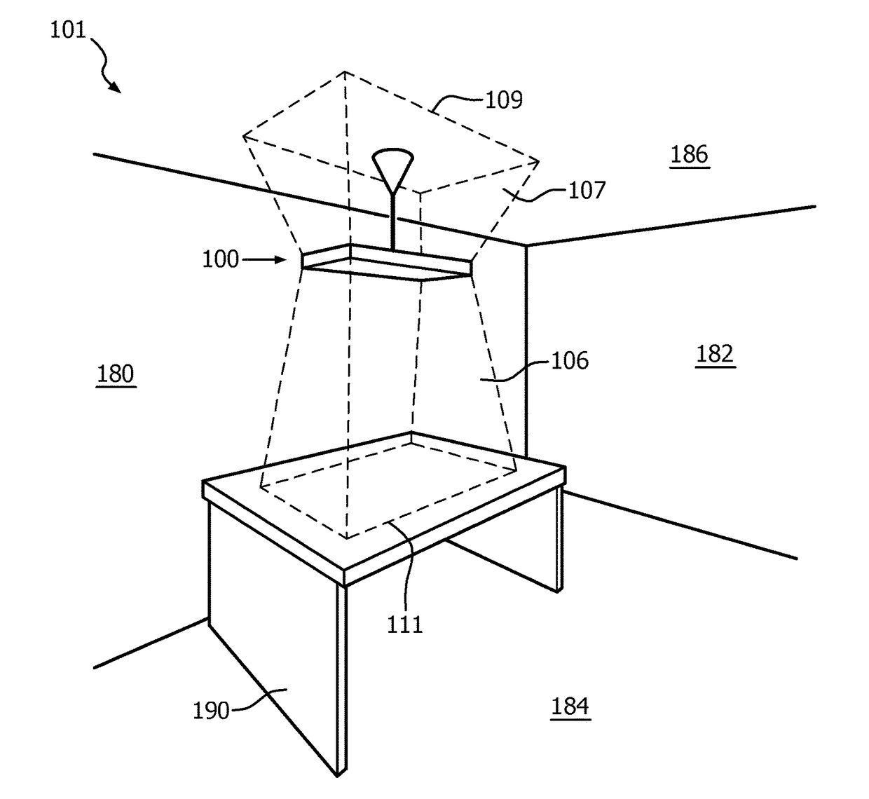
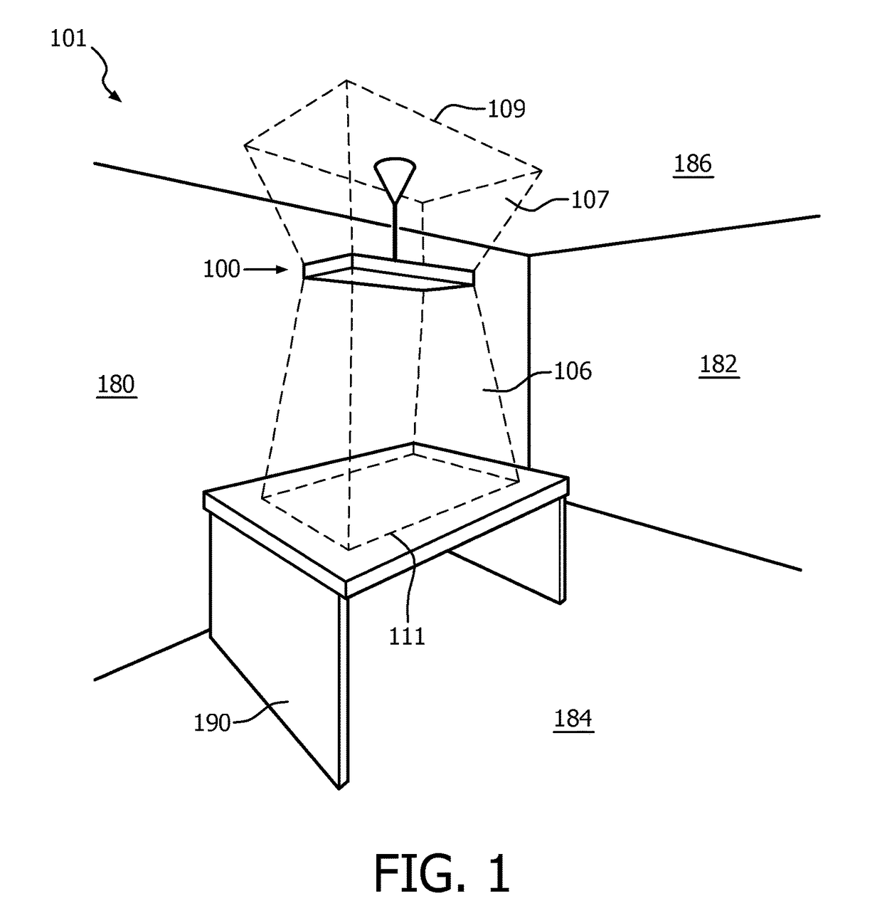
[0058]FIG. 1 shows a room 101 provided with a lighting device 100 according to a first embodiment of the invention. The room 101 comprises sidewalls 180, 182, floor 184 and ceiling 186. Furniture including for instance table 190 is arranged at certain predetermined locations on the floor. The lighting device comprises at least one first light source issuing a first, direct beam 106 in a first direction and at least one second light source issuing a second, indirect beam 107 in a second direction. Said first and second light source are dimmable and together issue light with a total light flux. At a mutually equal light flux of the first and the second beam, the glare level of the second beam is lower than the glare level of the first beam. The lighting device 100 according to the present invention comprises a preprogrammed controller (not shown) for controlling the lighting device. Said controller adjusts the light output of the respective light sources such that in a first illuminat...


PUM


Abstract

A lighting device comprising a first light source issuing a first beam and a second light source issuing a second beam. Said first and said second light source are dimmable and together issue light with a total light flux. At a mutually equal light flux of the first and the second beam, the glare level of the second beam is lower than the glare level of the first beam. The lighting device further comprises at least one (programmed) controller which, during operation, moderates said dim levels such that in at least a range of the illumination level a ratio of the dim level of the second beam to the dim level of the first beam increases in a gradual manner with increasing total light flux.

Description

CROSS-REFERENCE TO PRIOR APPLICATIONS[0001]This application is the U.S. National Phase application under 35 U.S.C. §371 of International Application No. PCT / IB14 / 058108, filed on Jan. 8, 2014, which claims the benefit of U.S. Provisional Patent Application No. 61 / 756,543, filed on Jan. 25, 2013. These applications are hereby incorporated by reference herein.TECHNICAL FIELD OF THE INVENTION[0002]The invention relates to a lighting device comprising at least one first light source issuing a first beam during operation of the first light source, and at least one second light source issuing a second beam during operation of the second light source, and in dependence on dim levels of the respective light sources said first and said second light source together issue light with a variable total light flux and variable illumination levels, and at a mutually equal light flux of the first beam and the second beam, the first beam and the second beam have a respective glare level, the glare le...

Claims


Application Information

Patent Timeline
Patent Type & Authority Patents(United States)
IPC IPC(8): H05B37/02H05B33/08F21V7/00F21S6/00F21S8/06H05B44/00
CPCH05B33/0851F21V7/0016H05B33/0854H05B33/0872H05B37/02H05B37/0227F21S6/008F21S8/06H05B45/20H05B47/10H05B47/105H05B47/11Y02B20/40
Inventor VISSENBERG, MICHEL CORNELIS JOSEPHUS MARIEVAN DER ZANDE, BIANCA MARIA IRMASCHLANGEN, LUCAS JOSEF MARIASCHOBBEN, DANIEL WILLEM ELISABETHVAN DE WOUW, INGEGEERDINCK, LEONIE MARIALANSBERGEN, REMCO ADRIANUS GERARDUSPASVEER, WILLEM FRANKE
Owner SIGNIFY HLDG BV
Why Eureka
Try Eureka