Method for aligning an acetabular cup

a technology of acetabular cup and acetabular slit, which is applied in the direction of prosthesis, joint implants, applications, etc., can solve the problems of excessive wear and failure of components, permanent dislocation of the head, and excessive wear of liner parts

Active Publication Date: 2017-05-30
HOWMEDICA OSTEONICS CORP
View PDF21 Cites 16 Cited by
  • Summary
  • Abstract
  • Description
  • Claims
  • Application Information

AI Technical Summary

Benefits of technology

The present invention is a method for aligning an acetabular cup in a patient during hip replacement surgery using a pre-operative lateral x-ray image and an orientation technology. The method uses a pre-operative standalone x-ray image and an intra-operative orientation technology to determine how the pelvis may have shifted during surgery and adjust the orientation of the cup accordingly. The invention helps to recreate the natural pelvic tilt angle and alleviate the need for unnatural positioning of the patient during surgery. The method uses a combination of digital imaging and orientation technology to improve the accuracy of the surgery and the patient's outcome.

Problems solved by technology

Should the stem and cup not be positioned / aligned accurately, the neck of the stem may impinge on the lip of the insert resulting in a levering action that could allow the femoral head to cam out of the insert resulting in a permanent dislocation of the head.
The impingement can also lead to excessive component wear and possibly failure.
In addition, a malpositioned cup can result in excessive liner wear even without impingement.
A shell with a high abduction (inclination) angle can have joint forces concentrated near the cup liner rim, thereby increasing the wear rate due to concentrated forces.
It has been found based on post-operative x-rays, however, that despite the alignment guide being parallel to the floor during insertion, of the acetabular cup, the resultant inclination or anteversion of the acetabulum in relation to the alignment guide is often different than expected and, thus, the acetabular cup has been installed at a less than ideal position.
Some of the drawbacks of this type of instrument are that the pelvis usually shifts when the patient is laid on the operating room table.
Another drawback is that the current antenna / impactor combination is set at set angles.
From a clinical perspective, the major drawbacks for navigation are that the technique involves placing invasive pins having the tracker thereon in the patient pelvis and femur.
Using pins results in multiple separate wounds and increases the possibility of infection.
This technique is also time intensive.
Some systems require a pre-op CT scan which is costly.
However, they do not aid the user by figuring out how the pelvis has shifted on the table as there is no algorithm to do this.
These current digital imaging systems do not have an algorithm that tries to compare pre-operative and intra-operative images to calculate how the intra-operative pelvic position changes in orientation to a pre-operative image.
Furthermore, the current digital systems don't calculate the cup impaction angles that would account for these changes.
Reorienting the shell could compromise the fit and security of the cup to the acetabular bone cavity.
Multiple reorientations could possibly compromise the fit to the point that a secure fit is no longer achieved.
The removal of further acetabular bone is not ideal as this could compromise the overall strength of the remaining bone, and reduce the amount of bone for any future revisions.

Method used


Image

  • Method for aligning an acetabular cup
  • Method for aligning an acetabular cup
  • Method for aligning an acetabular cup

Examples


example 1

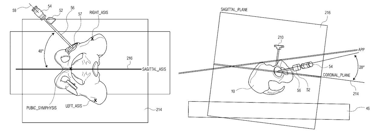
[0078]This example shows how the cup impactor is positioned relative to reference bar 40 to obtain the desired inclination and anteversion. The pelvis is shown in a perfect orientation similar to FIG. 8D.

[0079]Referring to FIGS. 9 and 9A there is shown a “perfect” pelvic orientation on table 46. Also shown is the acetabular cup impactor 54 with shaft 56 shown at a 45° inclination 0° anteversion and zero tilt, rotation and obliquity with respect to reamer or impactor 57.

[0080]As shown in FIGS. 9 and 9A pelvis 10 did not alter position from the A / P image (pelvis in a perfect position) when placed on table 46. The basic pelvis orientation is exactly 90° to the standing x-ray. The plane is normal to the table. This is shown by the 0° alignment between the planes of the two x-rays (pre-standing and intraoperative prone). The plane that the standing x-ray was taken at is shown with the line 59 of FIG. 9. The plane through line 59 is normal to the table. The impactor is placed in the reame...

example 2

[0082]Referring to FIGS. 10A and 10B, similar “perfect” pelvic orientation on the OR table as with Example 1. Standing x-ray plane is normal to the table shown with acetabular cup impactor at a now desired 45° inclination (FIG. 10A) and 20° anteversion (FIG. 10B). The cup impactor 54 would be oriented 45° from the reference bar 40 and 20° off the reference bar 40. The two navigation trackers 50, 52, one of the reference bar, and one on the impactor helps facilitate finding these angles for the impactor. The orientation is now 45 DEG INCLINATION, 20 ANTEVERSION, 0 TILT, 0 ROTATION and 0 OBLIQUITY.

example 3

[0083]Here the cup impactor orientation is 45° INCLINATION, 20° ANTEVERSION, AND THE PELVIC ORIENTATION IS 10° TILT (to be confirmed below), 0° ROTATION and 0° OBLIQUITY. Dimensions for calculations for determining amount of tilt are pre-op images are shown in FIGS. 11, 11A and 11B. Intra-op image: A / P image shown in FIG. 11A: May have tilt. This is to be verified by the calculation outlined below. A Pre-op A / P, preferably standing image is taken and shown in FIG. 11. An Intra-operative A / P image is taken and shown in FIG. 11A. The 3.179 dimension between points 24 and 35 is compared to the pre-op dimension of 2.599 between points 24 and 49. Since the 3.179 is greater than 2.599, it indicates that the pelvis has tilted forward (positive tilt) by a certain amount. Dimensions for calculations for determining amount of tilt: A pre-operative lateral image is shown in FIG. 11B with lengths B, C, and E and angle D.

[0084]Table 1 refers to the dimensions of FIGS. 11A and 11B.

[0085]

TABLE 1Le...


PUM


Abstract

A method is used for aligning an acetabular cup insertion instrument by taking a single lateral view pre-operative digital x-ray of a standing patient's pelvis. The natural pelvic tilt angle is determined by locating an anterior pelvic plane (APP) which is defined by first, second and third points on the anterior of the pelvis and determining the angle between the APP and a coronal plane perpendicular to the surface on which the patient is standing. The patient is then placed on a surface of an operating room table in a supine position. A position tracking device is placed on the patient's pelvis to track movement. Thereafter an operating room navigation or orientation system is used to relocate the APP defined by the first, second and third points. A cup insertion instrument having a position tracking device thereon is oriented using the navigation or orientation system.

Description

CROSS-REFERENCE TO RELATED APPLICATIONS[0001]This application is a continuation-in-part of U.S. patent application Ser. No. 14 / 038,033, filed Sep. 26, 2013, now U.S. Pat. No. 9,248,002 B2; the disclosure of which is incorporated herein by reference.BACKGROUND OF THE INVENTION[0002]Hip surgery requires the implantation of a femoral stem and an acetabular cup. The femoral stem has a spherical head that attaches to the neck of the stem and is free to articulate within a bearing insert that is fitted into the shell of an acetabular cup. Should the stem and cup not be positioned / aligned accurately, the neck of the stem may impinge on the lip of the insert resulting in a levering action that could allow the femoral head to cam out of the insert resulting in a permanent dislocation of the head. The impingement can also lead to excessive component wear and possibly failure.[0003]In addition, a malpositioned cup can result in excessive liner wear even without impingement. A shell with a high...

Claims


Application Information

Patent Timeline
Patent Type & Authority Patents(United States)
IPC IPC(8): A61F2/46A61B34/20A61B34/10
CPCA61F2/4609A61B34/10A61B34/20A61B2034/101A61B2090/376A61B2090/3966A61B17/1746A61F2002/4658A61F2002/4668A61B2034/2055A61B2034/2065A61B2034/2068A61B2034/2074A61B17/1666A61F2002/4681
Inventor MCCARTHY, THOMAS FRANCIS
Owner HOWMEDICA OSTEONICS CORP
Why Eureka
Try Eureka