Linear flow regulating apparatus for intravenous infusion

a flow regulating apparatus and flow regulating technology, applied in mechanical devices, process and machine control, instruments, etc., can solve the problems of deteriorating the accuracy of flow rate regulation, difficult to accurately regulate flow rate, and difficult to regulate flow rate, so as to facilitate accurate flow regulation, facilitate simple configuration, and quickly and accurately regulate flow rate

Active Publication Date: 2017-05-30
KOREA INST OF MACHINERY & MATERIALS
View PDF26 Cites 0 Cited by
  • Summary
  • Abstract
  • Description
  • Claims
  • Application Information

AI Technical Summary

Benefits of technology

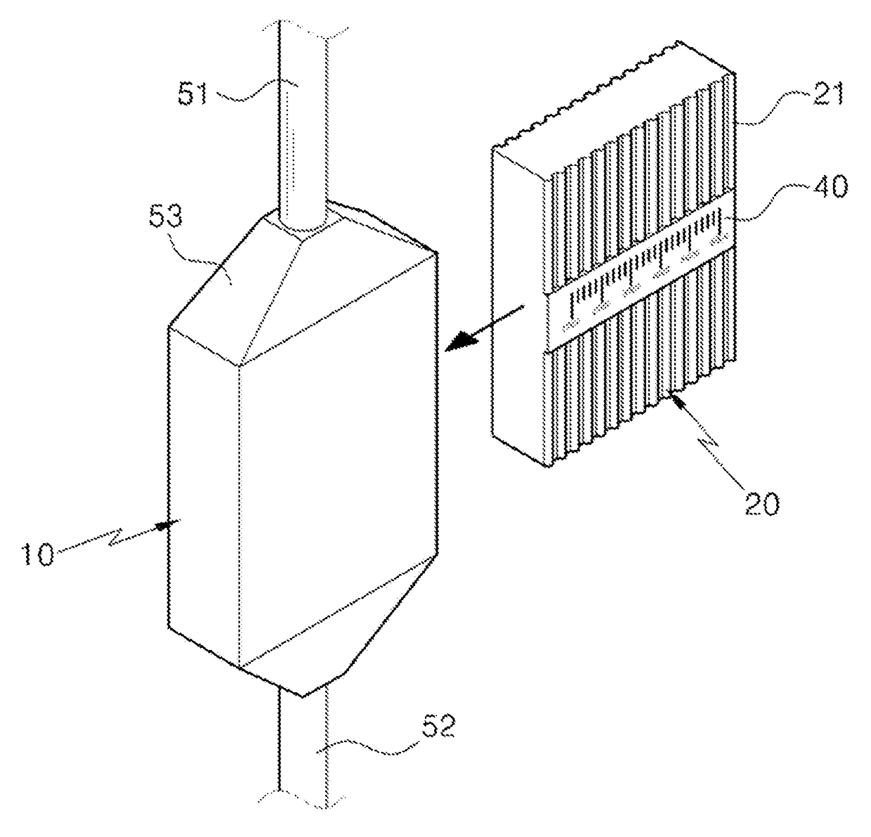
[0029]As discussed above, the linear flow regulating apparatus for intravenous infusion in accordance with the present invention has the advantage of enabling accurate flow regulation by linearly regulating the flow rate of a solution. The present invention makes it possible to quickly and accurately regulate the flow rate to a desired level by calibrating the number of drops from a drop chamber once, since the flow rate of the solution is maintained linear.
[0030]Moreover, the present invention has the advantage of simple configuration and ease use because the control unit is configured to be put in or taken out along the width of the flow channel unit.
[0031]Further, the present invention has the advantage of cutting down production costs, increasing production yield, and reducing costs incurred during production.

Problems solved by technology

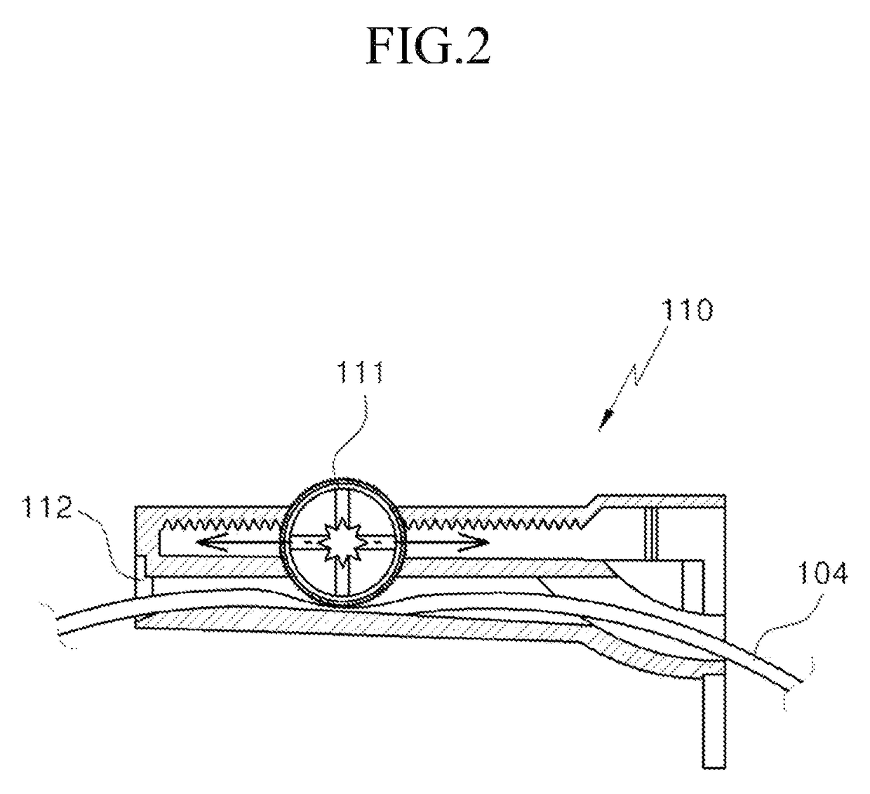
However, the roller clamp type infusion flow regulator 110 shown in FIGS. 1 and 2 is disadvantageous in that, since the flow rate should be measured while seeing the drip chamber 102 whenever the roller type manipulation unit 111 is moved, complicated measurements (drip rate counts) should be repeatedly performed, which will deteriorate the accuracy of flow rate regulation.
Moreover, the biggest problem of the conventional roller clamp type infusion flow regulator 110 is that it is difficult to regulate the flow rate.
This results in nonlinear flow regulation, and therefore it is difficult to accurately regulate the flow rate merely by varying the length or radius of the cylindrical tube.
As above, regulating the flow rate by variations in diameter and length is nonlinear and complex even in the cylindrical tube having quite a simple structure.
Moreover, variations in the cross-sectional area and length of the flow passage are even more complicated in the roller clamp type flow regulator, making flow regulation more difficult.
Although the roller clamp type flow regulator can vary the flow passage area by a roller, it is not capable of uniformly adjusting the dimension, shape, hydraulic radius, etc of the flow passage area.
Therefore, the roller clamp type flow regulator has the drawbacks that it is difficult to regulate the flow rate by the above-mentioned Equation 1, the roller for manipulation is easily moved at a fixed position, and a creep may occur in a deformed tube over time, causing a change in flow rate.
The rotary flow regulator also has the problem that it is difficult to regulate the flow rate according to the above-mentioned Equation 1 (the scale is nonlinear because the flow rate is inversely proportional to the length l of the capillary).
In addition, the constant infusion pump has the problems that it is not convenient to install and use it due to its large size, and runs a high risk of contamination because it is used on many people.

Method used


Image

  • Linear flow regulating apparatus for intravenous infusion
  • Linear flow regulating apparatus for intravenous infusion
  • Linear flow regulating apparatus for intravenous infusion

Examples


Embodiment Construction

[0039]Before exemplary embodiments of the present invention are described in detail, it will be understood that, detailed constitution and arrangements of elements described in the detailed description or illustrated in the drawings should not be construed as limiting the application of the invention. The invention may be embodied in many alternate forms and performed in various methods.

[0040]The terms or words to describe the direction of an apparatus or element (for example, “front”, “back”, “up”, “down”, “top”, “bottom”, “left”, “right” and “lateral”, among others) are used to simplify the description of the invention. It will be, therefore, understood that these terms do not mean that the relevant apparatus or element shall be only in the specific direction.

[0041]The present invention has the following features to attain the aspect mentioned above.

[0042]The present invention will now be described more fully hereinafter with reference to the accompanying drawings, in which prefer...


PUM


Abstract

The present invention relates to a linear flow regulating apparatus for intravenous infusion, and more particularly, to a flow regulating apparatus which is used in an infusion set for intravenous infusion to regulate the flow rate of a solution injected into a body. To eliminate the difficulties caused by the nonlinearity of conventional flow regulating apparatuses, which regulate flow rates by pressing a solution flow tube to adjust the flow passage area, the linear flow regulating apparatus has a control unit to be put in or taken out along the width of a flow channel unit through which the solution flows when the height and length of the flow channel unit are fixed, and is capable of linearly regulating the flow rate by varying the flow passage area of the flow channel unit by adjusting the width of a flow channel unit.

Description

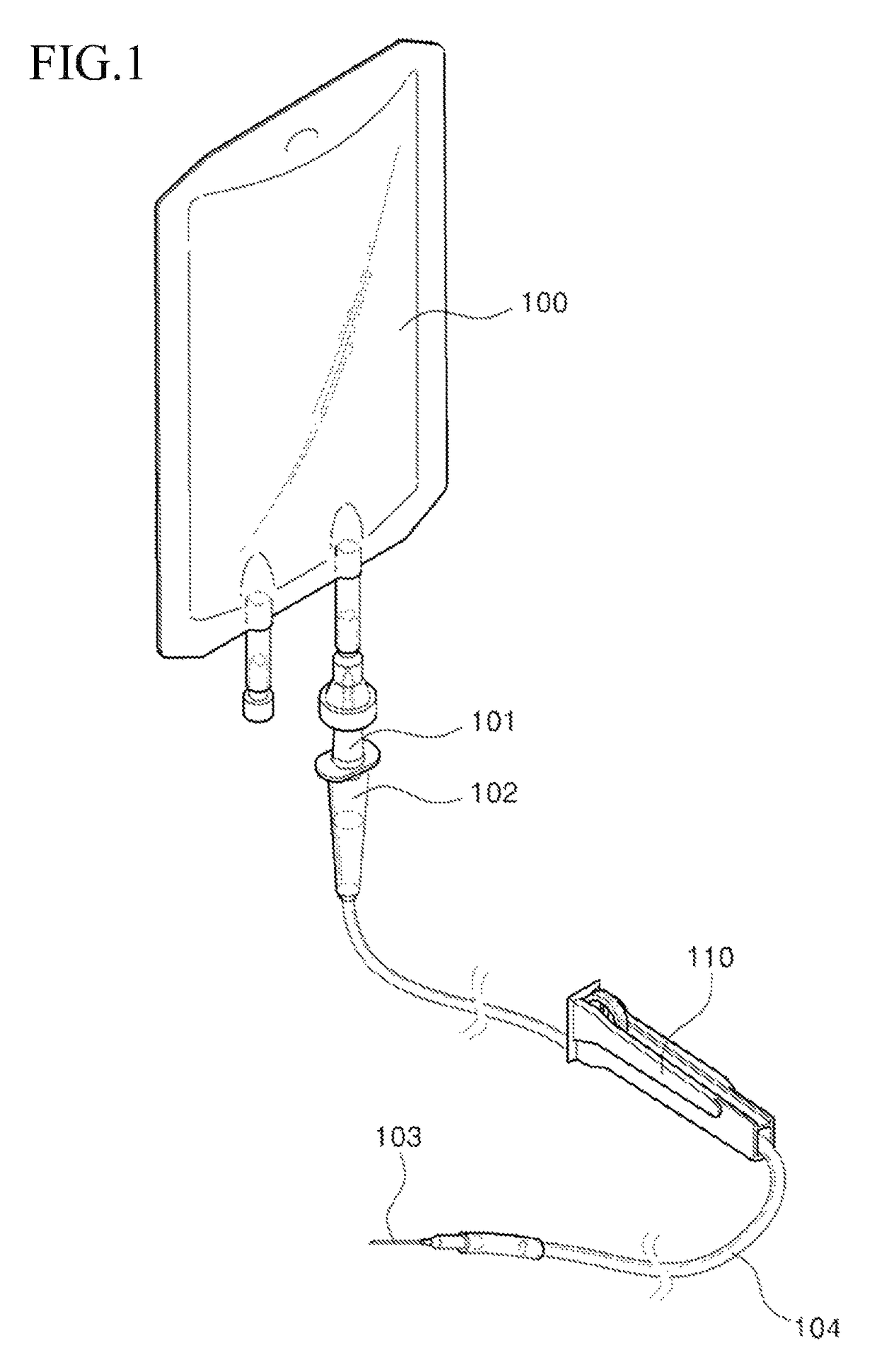
CROSS-REFERENCE TO RELATED APPLICATION[0001]This application claims priority to and the benefit of Korean Patent Application No. 10-2011-0120839 filed in the Korean Intellectual Property Office on Nov. 18, 2011 and PCT Application No. PCT / KR2012 / 009763 filed in the Korean Intellectual Property Office on Nov. 16, 2012, the entire contents of which are incorporated herein by reference.BACKGROUND OF THE INVENTION[0002](a) Field of the Invention[0003]The present invention relates to a flow regulating apparatus used for an intravenous infusion set (IV set), and more particularly to, a linear flow regulating apparatus which is capable of linearly regulating the flow rate of an infusion solution.[0004](b) Description of the Related Art[0005]As shown in FIG. 1, an intravenous injection system for intravenous administration of fluids includes an infusion solution bag 100 containing an infusion solution, an insertion spike 101 adapted to be inserted through a sealing plug of the infusion solu...

Claims


Application Information

Patent Timeline
Patent Type & Authority Patents(United States)
IPC IPC(8): A61M5/00A61M5/14A61M5/168A61M39/28F16K5/04
CPCA61M5/16813A61M5/1407A61M5/16881A61M5/141A61M39/287A61M2206/11F16K5/0414F16K37/0016F16K3/0281A61M5/168A61M5/14A61M39/28
Inventor YOON, EUI-SOOPARK, MOO-RYONGCHOI, BUM SEOGPARK, JUN YOUNGYOO, IL-SUSEO, JEONG MINHWANG, SOON-CHAN
Owner KOREA INST OF MACHINERY & MATERIALS
Why Eureka
Try Eureka