Threaded connection

a threaded connection and pipe technology, applied in the direction of screw threaded joints, drilling pipes, mechanical equipment, etc., can solve the problems of reducing the thickness of the connection compared to the rest of the pipe body, the connection is most likely to fail, and the efficiency of tension is limited, so as to reduce the deformation of the seal, reduce the width of the pin thread, and limit the axial movement of the connection

Active Publication Date: 2017-06-06
MARUBENI ITOCHU TUBULARS AMERICA
View PDF19 Cites 4 Cited by
  • Summary
  • Abstract
  • Description
  • Claims
  • Application Information

AI Technical Summary

Benefits of technology

[0008]In addition, the pin threads and the box threads are arranged so that when the connection is fully made up, the threads of the run-in pin thread portion engage the threads of the run-out box thread portion, the threads of the perfect pin thread portion engage the threads of the perfect box thread portion, the threads of the run-out box thread portion engage the threads of the run-in pin thread portion, the external pin seal surface sealingly engages the external box seal surface, and the internal pin seal surface sealingly engages the internal box seal surface. Furthermore, the width of the pin threads is slightly greater than the width between corresponding box threads, so that as the pin threads engage with the box threads, an interference fit is created between the pin threads and the box threads to limit axial movement in the connection under tension and compression and reduce deformation of the seals during full compression.
[0010]According to yet another embodiment of the invention, the crests of at least a portion of the box threads can be curved so that when the pin threads are fully engaged with the box threads, there is a void between the roots of the pin threads and the corresponding curved crests of the box threads to reduce standoff caused by lubricant or other fluids becoming trapped between the threads as the connection is made up.
[0015]In other example embodiments, the width of the pin threads can be slightly greater than the width between adjacent box threads, so that as the pin threads engage with the box threads, an interference fit is created between the pin threads and the box threads to limit axial movement in the connection under tension and compression and reduce deformation of the seals during full compression. Further, the crests of at least a portion of the box threads can be curved so that when the pin threads are fully engaged with the box threads, there is a void between the root of the pin threads and the corresponding curved crests of the box threads to reduce standoff caused by lubricant or other fluids becoming trapped between the threads as the connection is made up.
[0017]The pin threads and the box threads are arranged so that when the connection is fully made up, the threads of the run-in pin thread portion engage the threads of the run-out box thread portion, the threads of the perfect pin thread portion engage the threads of the perfect box thread portion, the threads of the run-out box thread portion engage the threads of the run-in pin thread portion, the external pin seal surface sealingly engages the external box seal surface, and the internal pin seal surface sealingly engages the internal box seal surface. In addition, the crests of at least a portion of the box threads being curved so that when the pin threads are fully engaged with the box threads, there is a void between the roots of the pin threads and the corresponding curved crests of the box threads to reduce standoff caused by lubricant or other fluids becoming trapped between, the threads as the connection is made up.
[0019]According to some alternate embodiments, the width of the pin threads can be slightly greater than the width between adjacent box threads, so that as the pin threads engage with the box threads, an interference fit is created between the pin threads and the box threads to limit axial movement in the connection under tension and compression and reduce deformation of the seals during full compression. In addition, the pin can further include a pin internal seal diameter, and a pin internal seal thickness, and the ratio of the pin internal seal diameter to the pin internal seal thickness can range from about sixteen to about sixty six.

Problems solved by technology

One reason that tension efficiency is limited to about the range described above, is because when an integral flush connection is machined, material is cut away from the pipe end to form the flush connection, which leads to a thinner pipe at the connection compared to the rest of the pipe body.
In threaded connections, there is typically a weak point, which is the point where the connection is most likely to fail.

Method used


Image

  • Threaded connection
  • Threaded connection
  • Threaded connection

Examples


Embodiment Construction

[0034]The foregoing aspects, features, and advantages of the present technology will be further appreciated when considered with reference to the following description of preferred embodiments and accompanying drawings, wherein like reference numerals represent like elements. In describing the preferred embodiments of the technology illustrated in the appended drawings, specific terminology will be used for the sake of clarity. However, the embodiments are not intended to be limited to the specific terms used, and it is to be understood that each specific term includes equivalents that operate in a similar manner to accomplish a similar purpose.

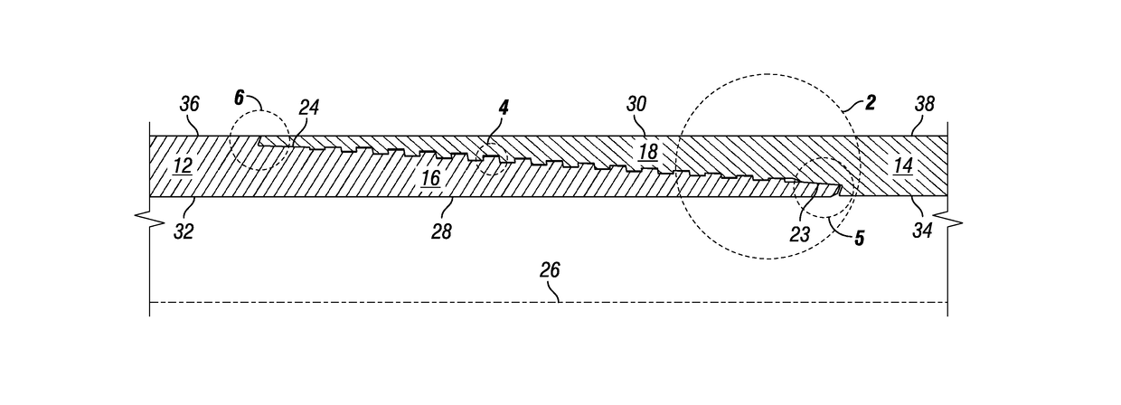
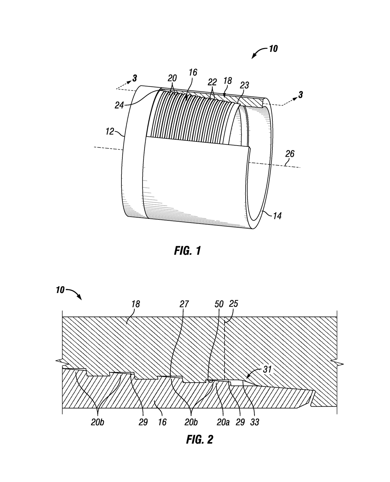
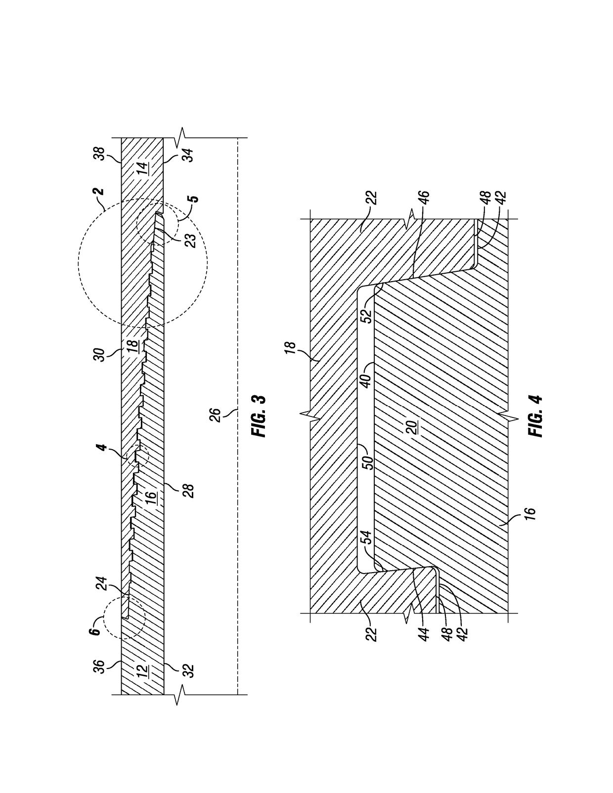
[0035]FIG. 1 depicts an isometric perspective view of an integral flush threaded connection 10 according to an example embodiment of the present technology. As used herein, the term “integral flush connection” or “flush connection” is used to refer to a connection that is machined into a pipe body without adding any additional material or up-...


PUM


Abstract

A threaded connection having a straight central axis, the connection including a plurality of pin threads, each pin thread having a root and a crest, and a box having a plurality of box threads, each box thread having a root and a crest. The crests of at least a portion of the box threads are curved so that when the pin threads are fully engaged with the box threads, there is a void between the roots of the pin threads and the corresponding curved crests of the box threads to reduce standoff caused by lubricant or other fluids becoming trapped between the threads as the connection is made up.

Description

[0001]This application claims priority to and the benefit of U.S. Provisional Patent Application Ser. No. 61 / 916,621, which was filed Dec. 16, 2013, the fell disclosure of which is hereby incorporated herein by reference in its entirety.FIELD OF THE INVENTION[0002]The present technology relates, to threaded connections for pipes, and in particular to threaded connections for pipes that carry oil and gas and that have an increased ability to withstand stress forces.BACKGROUND[0003]Pipes used, for example, in oilfield pipelines, have been joined end-to-end to transport oil or other fluids from place to place. Typically, the ends of the pipes are joined by threading together the male end of one of the pipes, known as a pin, with the female end of the other pipe (known as the box). There are a number of different types of connections. Some connections are known as integral flush connections, wherein the connection is machined into the pipe body, without adding any additional material, o...

Claims


Application Information

Patent Timeline
Patent Type & Authority Patents(United States)
IPC IPC(8): F16L25/00E21B17/042F16L15/00F16L15/06
CPCE21B17/042F16L15/004F16L15/06
Inventor DEHART, CODY ALLEN
Owner MARUBENI ITOCHU TUBULARS AMERICA
Why Eureka
Try Eureka