Fluid line

a technology of flue gas and line, which is applied in the direction of machines/engines, thin material processing, exhaust treatment, etc., can solve the problems of reducing the mass of the vehicle, reducing the cross section of the through-channel, and reducing the flow rate of the vehicle, so as to reduce the cross-section of the through-channel and prevent the production of the connection

Active Publication Date: 2017-06-06
NORMA GERMANY GMBH
View PDF34 Cites 9 Cited by
  • Summary
  • Abstract
  • Description
  • Claims
  • Application Information

AI Technical Summary

Benefits of technology

[0011]The liquid flowing through the fluid line can at most fill the flow cross section. If the flow cross section inside the connector is smaller, then at this point there is also less liquid present that can freeze. The smaller the volume of the liquid that can freeze, the quicker this liquid volume can be thawed. Furthermore, the increase in volume during the freezing of the liquid is also dependent on the liquid volume. Thus a smaller volume expands much less markedly than a larger volume. The danger of damage to the connector by liquid that expands during freezing is therefore kept lower.
[0013]Preferably, the heating device is embodied as a heater rod, which is guided out of the pipe into the pipe connection of the connector and reduces the flow cross section of the through-channel in the interior of the pipe connection. The heater rod thus fulfills two functions. On the one hand, the heater rod is able to generate heat that can then be introduced directly into the liquid present in the fluid line. It is therefore not necessary for this heat also to penetrate the material of the connector or of the pipe. On the other hand, the heater rod fills a part of the free space in the interior of the connector. Where the heater rod is present, no liquid can be present and freeze.
[0014]Preferably, the heater rod is embodied in a bendable manner. The heater rod thus has the advantage that it can also be inserted into a pipe that does not have a straight course. On the other hand, this embodiment has the advantage that the heater rod can be guided laterally out of the connector when the through-channel has a straight-line course. In this case, although the heater rod does not fill the entire through-channel in part, but only a part of the length of the through-channel, this is not critical, since the heater rod needs only to thaw a relatively small volume of liquid. As soon as the liquid is thawed, it can transport heat to frozen regions of the liquid so that a correspondingly short thawing can be achieved.
[0015]Preferably, the connector has a heater outlet channel that forms an angle unequal to 0° with the through-channel, wherein a ramp element is arranged in the through-channel, which ramp element has a guide surface pointing out of the through-channel to the heater outlet channel and reduces the cross section of the through-channel on the other side of the pipe connection. The ramp element also has two functions. When the heater rod is guided through the pipe connection into the interior of the connector, it is deflected by the guide surface into the heater outlet channel so that it does not reach a connection geometry and there impede the production of a connection between the connector and a counter element. On the other hand, the ramp element also contributes to a reduction in volume in the interior of the connector. Where the ramp element is located there can no longer be any liquid that can freeze. The ramp element is located at a position at which the heater rod has already been deflected so that it is no longer directly available for heating the liquid in the interior of the connector. Accordingly, the ramp element also establishes favorable conditions with respect to the reduction of the liquid volume to be heated.
[0019]Preferably, a gap with a maximum extension of 1 mm perpendicular to an axis of the through-channel is provided between a circumferential wall delimiting the through-channel inside the pipe connection and the heater rod. Thus a liquid layer between the heater rod and the pipe connection, or a corresponding ice layer, has a maximum thickness of 1 mm. Therefore the ice layer can be thawed correspondingly quickly.

Problems solved by technology

When a fluid line of this type is installed in a motor vehicle, there is the danger at low outdoor temperatures that the urea will freeze in the fluid line so that it can no longer flow.
This increases the mass of the vehicle and increases the energy consumption.
While the pipe generally has a certain flexibility so that it can generally absorb the increase in volume associated with the freezing of the liquid inside the fluid line without any difficulty, the connector is not usually so resilient.
There is therefore a danger of the connector being damaged due to the freezing of the liquid.

Method used


Image

  • Fluid line
  • Fluid line
  • Fluid line

Examples


Embodiment Construction

[0045]The particulars shown herein are by way of example and for purposes of illustrative discussion of the embodiments of the present invention only and are presented in the cause of providing what is believed to be the most useful and readily understood description of the principles and conceptual aspects of the present invention. In this regard, no attempt is made to show structural details of the present invention in more detail than is necessary for the fundamental understanding of the present invention, the description taken with the drawings making apparent to those skilled in the art how the several forms of the present invention may be embodied in practice.

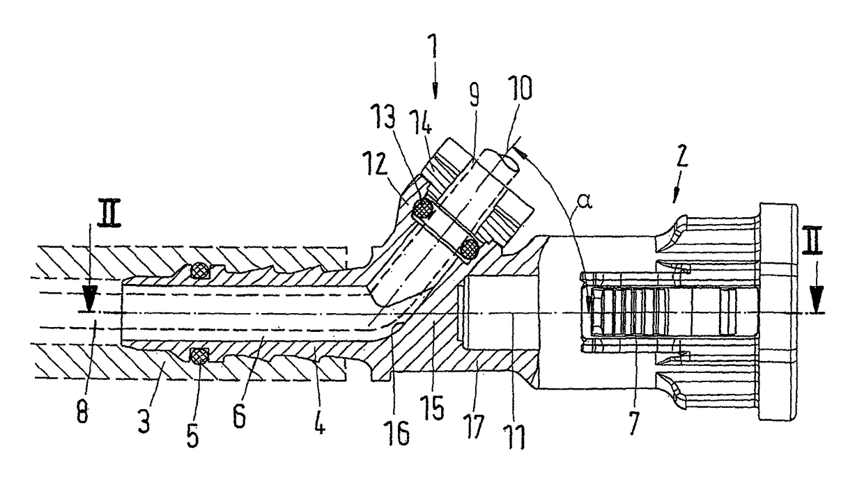
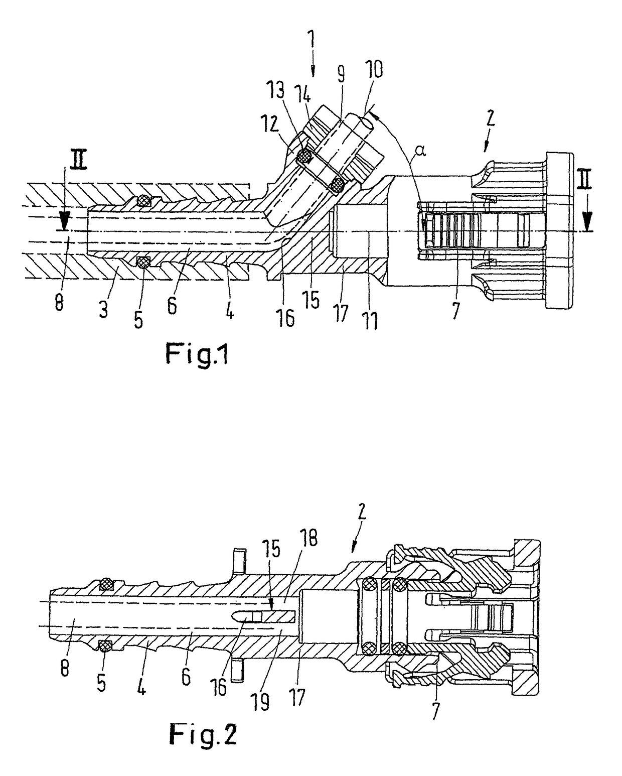
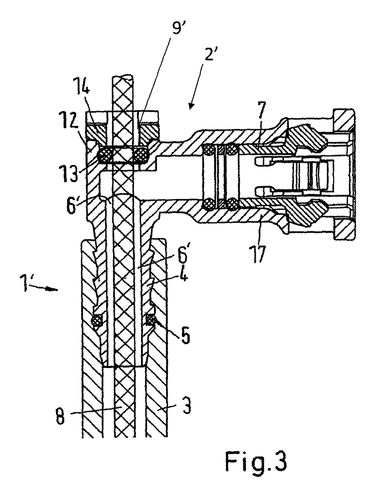
[0046]FIG. 1 shows a heatable fluid line 1 with a connector 2 and a pipe 3. The pipe is flexible. It can be made of an extruded plastic or also of a hose material. A hose is also to be covered by the term “pipe” below.

[0047]The pipe 3 is pushed onto a pipe connection 4 of the connector and sealed there with an O-ring 5. T...


PUM

PropertyMeasurementUnit
angleaaaaaaaaaa
temperatureaaaaaaaaaa
thicknessaaaaaaaaaa

Abstract

A fluid line includes a pipe, a connector having a pipe connection arranged at one end of the pipe, and a through-channel through the connector, wherein the pipe connection surrounds a portion of the through-channel, and a heater structured and arranged within the pipe and the connector to heat at least a portion of the pipe and at least a portion of the connector. A flow cross section of the through-channel section at least on a part of its length is no more than 60% of a flow cross section of the pipe.

Description

CROSS-REFERENCE TO RELATED APPLICATIONS[0001]The present application claims priority under 35 U.S.C. §119 of German Patent Application No. 10 2011 102 148.9, filed on May 20, 2011, the disclosure of which is expressly incorporated by reference herein in its entirety.BACKGROUND OF THE INVENTION[0002]1. Field of the Invention[0003]The invention relates to a fluid line with a pipe, a connector that has a pipe connection and that is arranged at one end of the pipe, and a heating device that heats at least a part of the pipe and at least a part of the connector, wherein the pipe connection surrounds a part of a through-channel through the connector.[0004]The invention is explained below based on a fluid line that is used to transport urea from a storage container to a point of consumption. Urea is used with diesel engines in order to reduce the emission of nitrogen oxides.[0005]2. Discussion of Background Information[0006]When a fluid line of this type is installed in a motor vehicle, th...

Claims


Application Information

Patent Timeline
Patent Type & Authority Patents(United States)
IPC IPC(8): F16L53/00F16L53/38F16L53/30
CPCF16L53/008F16L53/001F01N2610/10Y10T29/49826Y10T137/6606F16L53/30F16L53/38
Inventor ECKARDT, CARSTENMANN, STEPHANRASTETTER, MARCREAD, CAMERONSEIBEL, KNUT
Owner NORMA GERMANY GMBH
Why Eureka
Try Eureka