Apparatus for heat-treating powder particles and method of producing toner
What is AI technical title?
AI technical title is built by PatSnap AI team. It summarizes the technical point description of the patent document.
a technology for powder particles and heat treatment, applied in lighting and heating apparatus, instruments, developers, etc., can solve problems such as difficulty in uniform heat treatment of powder particles
Inactive Publication Date: 2017-06-06
CANON KK
View PDF21 Cites 27 Cited by
Summary
Abstract
Description
Claims
Application Information
AI Technical Summary
This helps you quickly interpret patents by identifying the three key elements:
Problems solved by technology
Method used
Benefits of technology
Benefits of technology
[0021]According to the present invention, it is possible to obtain the toner particles containing fewer coarse particles or less toner fine powder and having a sharp particle size distribution. Further, it is possible to obtain the toner particles having a circularity distribution within an appropriate range and having a sharp circularity distribution.
[0022]Further features of the present invention will become apparent from the following description of exemplary embodiments with reference to the attached drawings.
Problems solved by technology
However, in a conventional apparatus for heat treatment, the amount of heat which powder particles receive varies depending upon the position through which the powder particles pass, and hence it is difficult to heat-treat powder particles uniformly.
Method used
Image
Click on the blue label to locate the original text in one second.
Reading with bidirectional positioning of images and text.
Examples
example 1
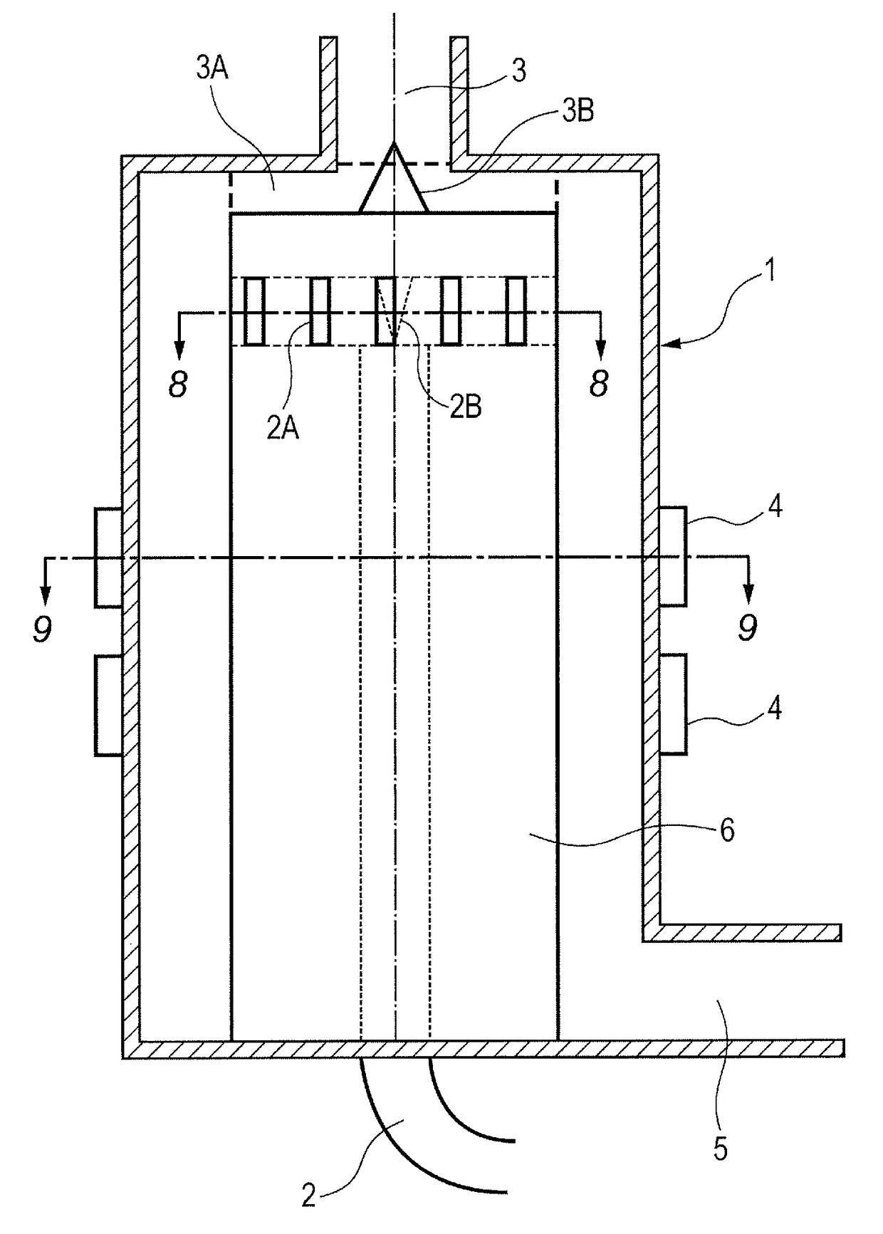
[0153]In this example, the toner particles a and the toner particles A were heat-treated through use of the apparatus for heat treatment illustrated in FIG. 1.
[0154]It should be noted that the inner diameter (diameter) of the main body of the apparatus for heat treatment is 450 mm, the outer diameter (diameter) of the center pole is 330 mm, and the height from a top board of the apparatus to a bottom board thereof is 1,350 mm. The outlet portion (2A) for the raw materials is divided into eight.
[0155]First, the supply amount of the toner particles a was set to 40 kg / hr, and the operation conditions of the apparatus were adjusted so that the average circularity of the particles after a heat treatment became 0.970. The operation conditions at this time were as follows. The hot air temperature was set to 165° C. and the hot air flow rate was set to 25.5 m3 / min. Further, the cold air temperature was set to −5° C. and the injection air flow rate was set to 3.0 m3 / min. The total air amount...
example 2
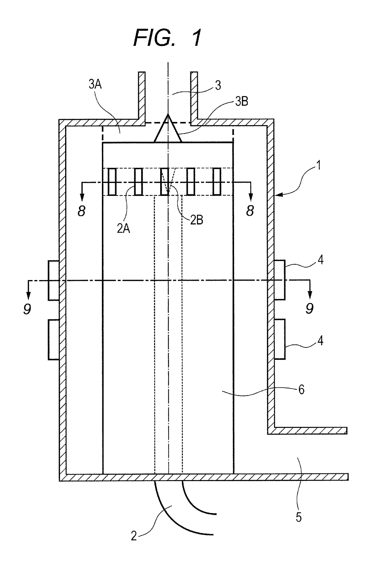
[0187]In this example, the apparatus for heat treatment illustrated in FIG. 2 was used.
[0188]In the structure of FIG. 2, multiple hot air supply units were provided, and hot air was introduced in four divided portions from a tangent direction of a horizontal surface in an upper part of the apparatus (see FIG. 10). The outlet portion (2A) for the raw materials was divided into eight.
[0189]In the above-mentioned structure, the toner particles A were heat-treated under the operation conditions shown in Table 1.
[0190]The results are summarized in Table 2.
example 3
[0191]In this example, the apparatus for heat treatment illustrated in FIG. 3 was used.
[0192]In the structure of FIG. 3, the hot air supply unit was provided slightly below the lower end of the raw material outlet portion (in this case, 10 mm below the raw material outlet portion), and hot air was introduced from a tangent direction of a horizontal surface of the apparatus in four divided portions. The raw material outlet portion (2A) was divided into eight.
[0193]In the above-mentioned structure, the toner particles A were heat-treated under the operation conditions shown in Table 1.
[0194]The results are summarized in Table 2.
PUM
Property
Measurement
Unit
temperature
aaaaa
aaaaa
temperature
aaaaa
aaaaa
specific surface area
aaaaa
aaaaa
Abstract
Provided is an apparatus for heat treatment capable of heat-treating toner particles efficiently and uniformly while suppressing increase of coarse particles due to coalescence, to thereby enable stable toner production. The apparatus for heat-treating powder particles each of which contains a binder resin and a colorant includes: a cylindrical treatment chamber in which the powder particles are heat-treated; a columnar member (6) provided so as to protrude from a lower end part of the treatment chamber toward an upper end part thereof; a powder particle supply unit (2) for supplying the powder particles to the treatment chamber; a hot air supply unit (3) for heat-treating the supplied powder particles; and a collection unit (5) for collecting the heat-treated powder particles discharged outside the treatment chamber through a toner discharge port provided on the lower end part side of the treatment chamber. The hot air supply unit is provided so that the hot air is supplied along an inner circumferential surface of the treatment chamber. The powder particle supply unit includes multiple particle supply ports provided on an outer circumferential surface of the columnar member. The toner discharge port is provided in an outer circumferential portion of the treatment chamber so as to keep a rotation direction of the powder particles.
Description
TECHNICAL FIELD[0001]The present invention relates to an apparatus for heat-treating powder particles, for producing toner to be used in an image forming method such as an electrophotographic method, an electrostatic recording method, an electrostatic printing method, or a toner jet system recording method, and to a method of producing toner using the apparatus.BACKGROUND ART[0002]In order to produce toner with appropriate circularity, there has been proposed an apparatus for heat-treating powder particles to spheroidize a shape of toner appropriately. However, in a conventional apparatus for heat treatment, the amount of heat which powder particles receive varies depending upon the position through which the powder particles pass, and hence it is difficult to heat-treat powder particles uniformly.[0003]In order to overcome the above-mentioned problem, an apparatus for heat treatment has been proposed, in which a powder particle supply portion is provided at the center of the appara...
Claims
Application Information
Patent Timeline
Application Date:The date an application was filed.
Publication Date:The date a patent or application was officially published.
First Publication Date:The earliest publication date of a patent with the same application number.
Issue Date:Publication date of the patent grant document.
PCT Entry Date:The Entry date of PCT National Phase.
Estimated Expiry Date:The statutory expiry date of a patent right according to the Patent Law, and it is the longest term of protection that the patent right can achieve without the termination of the patent right due to other reasons(Term extension factor has been taken into account ).
Invalid Date:Actual expiry date is based on effective date or publication date of legal transaction data of invalid patent.

