Heat treatment apparatus and method for manufacturing toner

a technology of heat treatment apparatus and toner, which is applied in the direction of heating apparatus, lighting and heating equipment, instruments, etc., can solve the problems of reducing the cleanability, reducing the efficiency of toner production, and affecting the quality of toner, so as to suppress the ratio of particles, reduce the amount of fine powder, and reduce the effect of spheroidization

Inactive Publication Date: 2015-07-07
CANON KK
View PDF33 Cites 28 Cited by
  • Summary
  • Abstract
  • Description
  • Claims
  • Application Information

AI Technical Summary

Benefits of technology

[0016]The present invention can provide a heat treatment apparatus which suppresses the coarsening of particles and can provide particles that have less fine powder and a sharp particle size distribution, even when the treatment amount of powder particles has been increased; and a method for manufacturing a toner, which enables the same. The present invention can also provide a heat treatment apparatus which gives a sharp distribution (small standard deviation) of a degree of circularity to the particles to be obtained, and can suppress the ratio of particles that have been excessively spheroidized; and a method for manufacturing a toner, which enables the same.
[0017]Further features of the present invention will become apparent from the following description of exemplary embodiments with reference to the attached drawings.

Problems solved by technology

However, in the method of modifying the surface by using heat, when more heat than is necessary is applied to the toner, the toners fuse with each other and occasionally produce coarse particles.
However, when an average degree of circularity of the toner is high, excessively spheroidized toner particles generally increase in the toner, and thereby, cleanability tends to be lowered.
This is because the excessively spheroidized toner particles easily pass through a cleaning blade.
Techniques for preventing the toner particles from passing through the cleaning blade include increasing the contact pressure of the cleaning blade, but the technique has a limit because of causing a harmful effect such as the increase of the running torque of a drum and the wear of the cleaning blade.
Incidentally, it is proved from a recent investigation that when the frequency of the particles with the degree of circularity of 0.990 or more in the distribution of the degree of circularity of the toner exceeds 20%, a cleaning failure tends to occur easily.
However, when the toner particles are heat-treated by using the technique described in PTL 1, the toner particles are nonuniformly heat-treated, and accordingly the heat-treated toner particles and untreated toner particles result in being mixed.
However, in the structure described in PTL 4, the toner is injected toward the hot air and also toward the center part of the apparatus, and accordingly it is concerned that the heat-treated toners collide with each other before being solidified and the coalescing particles increase.

Method used


Image

  • Heat treatment apparatus and method for manufacturing toner
  • Heat treatment apparatus and method for manufacturing toner
  • Heat treatment apparatus and method for manufacturing toner

Examples


example 1

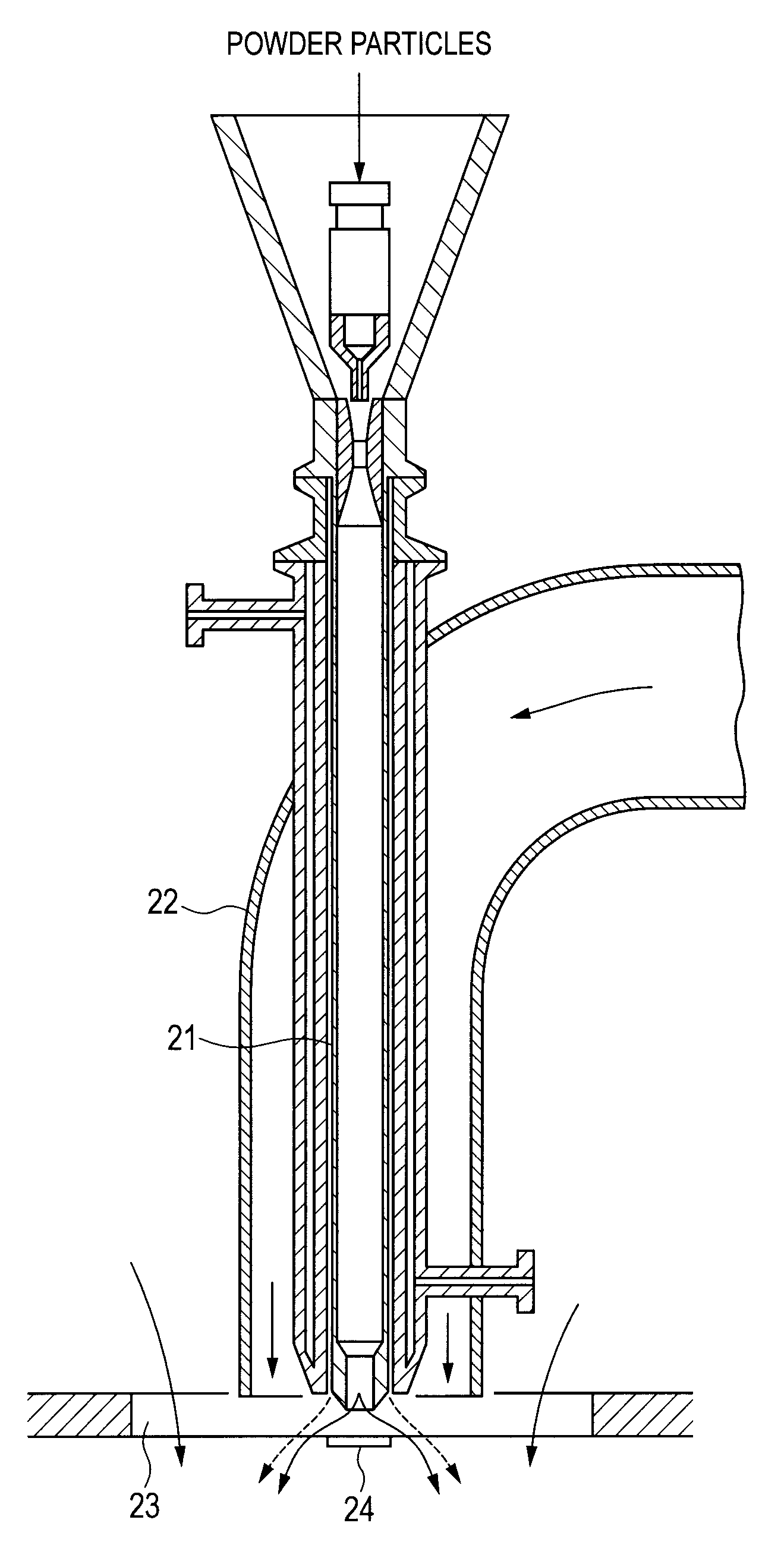
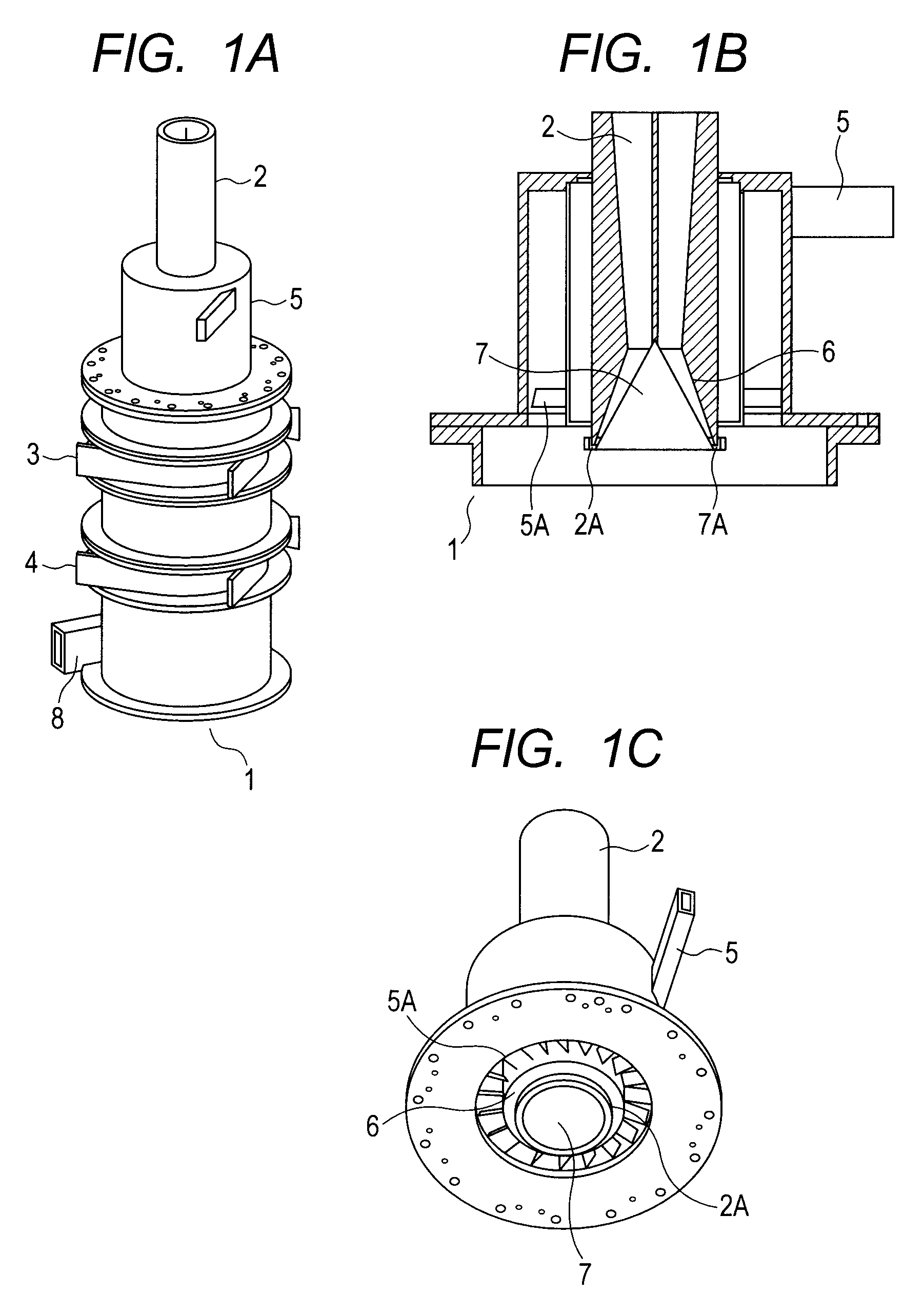
[0099]Powder particles were heat-treated with the use of a heat treatment apparatus illustrated in FIGS. 1A to 1C.

[0100]In the apparatus used in the present exemplary embodiment, a hot-air supply unit and a first nozzle were integrally formed. A louver was provided between a first nozzle and a second nozzle in the outlet portion of the hot-air supply unit so that thereby hot air flowed while spirally rotating along the inner wall face of the apparatus. Furthermore, in the cross-section of the apparatus, an angle formed by the ridge line of the first nozzle (angle spreading toward the downstream side from the upstream side of the apparatus) was set at 40 degrees, an angle formed by the ridge line of the second nozzle was set at 60 degrees, and a return portion was provided on the lower end of the second nozzle. An angle formed by the ridge line of the return portion was set at 140 degrees.

[0101]The powder particles A were heat-treated so that the average degree of circularity of the ...

example 2

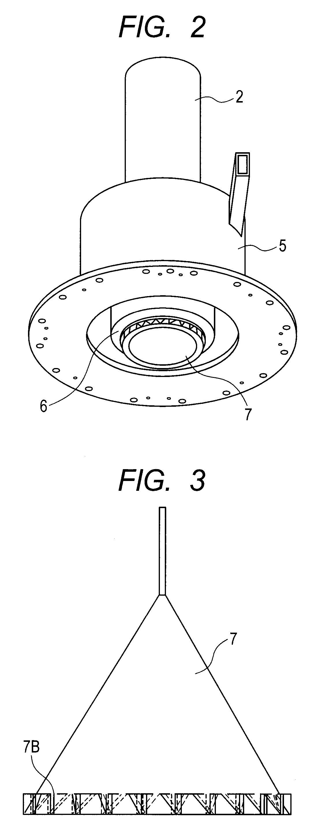
[0130]Powder particles A were heat-treated with the use of an apparatus illustrated in FIG. 2. The apparatus used in the present exemplary embodiment had such a structure that an adjustment portion of a raw-material supply unit was removed from the apparatus used in the Exemplary Embodiment 1.

[0131]The powder particles A were heat-treated so that the average degree of circularity of the powder particles A after having been heat-treated became 0.970, by using the apparatus having the above described structure.

[0132]As for the operation conditions at this time, the feed amount (F)=15 kg / hr, the temperature of hot-air (T1)=160° C., the quantity of hot-air (Q1)=10.0 m3 / min, the total quantity of cold-air 1 (Q2)=4.0 m3 / min, the total quantity of cold-air 2 (Q3)=4.0 m3 / min, the quantity of a compression gas (IJ)=1.5 m3 / min, the air quantity of a blower (Q4)=21.5 m3 / min, and the operation period of time was set at 1 hour.

[0133]These operation conditions were summarized in Table 1.

[0134]As ...

example 3

[0139]The apparatus used in the present exemplary embodiment was provided with a second nozzle having a shape (having ribs provided in the end of the nozzle and having no return portion) illustrated in FIG. 3. The apparatus had the same structure as the apparatus used in Exemplary Embodiment 1, except the above point.

[0140]The powder particles A were heat-treated so that the average degree of circularity of the powder particles A after having been heat-treated became 0.970, by using the apparatus having the above described structure.

[0141]As for the operation conditions at this time, the feed amount (F)=15 kg / hr, the temperature of hot-air (T1)=170° C., the quantity of hot-air (Q1)=10.0 m3 / min, the total quantity of cold-air 1 (Q2)=4.0 m3 / min, the total quantity of cold-air 2 (Q3)=4.0 m3 / min, the quantity of a compression gas (IJ)=1.4 m3 / min and the air quantity of a blower (Q4)=21.0 m3 / min, and the operation period of time was set at 1 hour.

[0142]These operation conditions were sum...


PUM

PropertyMeasurementUnit
weight average particle diameteraaaaaaaaaa
particle diameteraaaaaaaaaa

Abstract

An object of the present invention is to suppress the increase of coarse particles due to the fusion of powder particles and reduce a ratio of particles that have been excessively spheroidized, when the powder particles are heat-treated. A heat treatment apparatus including a raw-material supply unit, a hot-air supply unit for heat-treating a raw material and a discharge portion for discharging the heat-treated powder particles, and supplying hot air toward a raw material to be supplied from the raw-material supply unit, wherein the hot-air supply unit has a first nozzle and a second nozzle which spread in the radial direction downward from an upstream side in a hot-air supply direction, the second nozzle is arranged in the inside of the first nozzle, the hot air passes through a space between the first nozzle and the second nozzle, and an air-flow adjustment unit section for rotating the supplied hot air spirally along an inner wall face of the apparatus is provided in an outlet portion of the hot-air supply unit.

Description

TECHNICAL FIELD[0001]The present invention relates to a heat treatment apparatus for powder particles, and a method for manufacturing a toner.BACKGROUND ART[0002]In order to enhance the developing properties and the like of a toner, the surface of toner particles is modified by heat treatment. PTL 1 describes a method for spraying and dispersing powder particles into hot air with compressed air, thereby modifying the surface, and spheroidizing the particles. PTL 2 describes a method for adding an additive such as silica to the powder particles, then subjecting the powder particles to heat treatment to fix the additive onto the powder particles, and thereby removing the liberated additive.[0003]However, in the method of modifying the surface by using heat, when more heat than is necessary is applied to the toner, the toners fuse with each other and occasionally produce coarse particles. In order to efficiently and stably manufacture surface-modified particles for the toner, which do ...

Claims


Application Information

Patent Timeline
Patent Type & Authority Patents(United States)
IPC IPC(8): F26B21/00F26B17/16B01J19/26F26B17/12G03G9/08F26B3/10
CPCG03G9/0815G03G9/0804G03G9/0806G03G9/0819F26B17/12F26B17/16G03G9/0827B01J19/26F26B3/10B01J2219/00119B01J2/00G03G9/087
Inventor MINAGAWA, HIRONORIMIZO, YUICHIOHTSU, TAKESHIHAGIWARA, JUNICHITAMURA, YASUSHI
Owner CANON KK
Why Eureka
Try Eureka