Rotary parlour arranged to house animals to be milked

a technology of rotating parlours and cows, which is applied in the field of rotary parlours, can solve the problems of robot arms coming into contact with the rear leg of cows, cow injuries, and the risk of robot arms being damaged by cows

Active Publication Date: 2017-06-13
DELAVAL HLDG AB
View PDF55 Cites 6 Cited by
  • Summary
  • Abstract
  • Description
  • Claims
  • Application Information

AI Technical Summary

Benefits of technology

[0004]The object of the present invention is to provide a rotary parlour, where a robot arm has to extend past at least one portion of the animal during an attaching process of the teat cups, where the risk that the robot arm being damaged or the animal injured is substantially eliminated.
[0005]This object is obtained, according to the invention, by the feature that the rotary parlour comprises restricting means adapted to restrict the mobility of the animal in the milking stall in a manner such that a free space is created between the animal and the side wall element in a part of the milking stall. By restricting the mobility of the animal in the milking stall in a suitable manner, it is possible to create a free space which is not occupied by any portion of the animal. It is preferable by many reasons to create such a free space at the side wall element of the milking stall. A robot arm using this free space does not risk coming in contact with said portion of the animal during the attaching process. The risk that the robot arm is being damaged by the animal or that the animal is being injured by the robot arm is thereby substantially eliminated.
[0008]According to an embodiment of the invention, said restricting element is movably arranged in the milking stall between a non-active position in which it does not substantially restrict the mobility of the animal in the milking stall and an active position in which it restricts the mobility of the animal in the milking stall such that said free space is created. By means of such a restricting element, it is possible to restrict the movability of the animal in the milking stall and create said free space only temporary. During other times, the restricting means does not restrict motions of the animal in the milking stall. The restricting means may comprise a power member adapted to move the restricting element between the non-active position and the active position. Such a power member may be a hydraulic cylinder or a pneumatic cylinder. The restricting means may also be constituted by inflatable members. A further advantage with such restricting means is that animals of different sizes might be milked and treated in the milking stall.
[0011]According to a further embodiment of the invention, the storing device may be adapted to hold the teat cups in parking positions above the platform. Preferably, the storing device holds the teat cups in a parking position above the platform on one side of the animal and in a position situated in front of the rear legs and behind the front legs. In this case, the teat cups are parked in the storing device relatively close to the udder of the animal. Such a positioning of the storing device result in a relatively short pull out length of the milking tubes of the teat cups. Thereby, the risk is reduced that the milk tubes of the teat cups become entangled with each other. Preferably, the storing device is positioned in the vicinity of the side wall element. The storing device may comprise a part of it. The storing device may be attached to the side wall element or to a floor surface of the platform.

Problems solved by technology

It is here a risk that the robot arm comes in contact with a rear leg of the cow.
In this case, it is a risk that the robot arm is being damaged by the cow or the cow is being injured by the robot arm.

Method used


Image

  • Rotary parlour arranged to house animals to be milked
  • Rotary parlour arranged to house animals to be milked
  • Rotary parlour arranged to house animals to be milked

Examples


Embodiment Construction

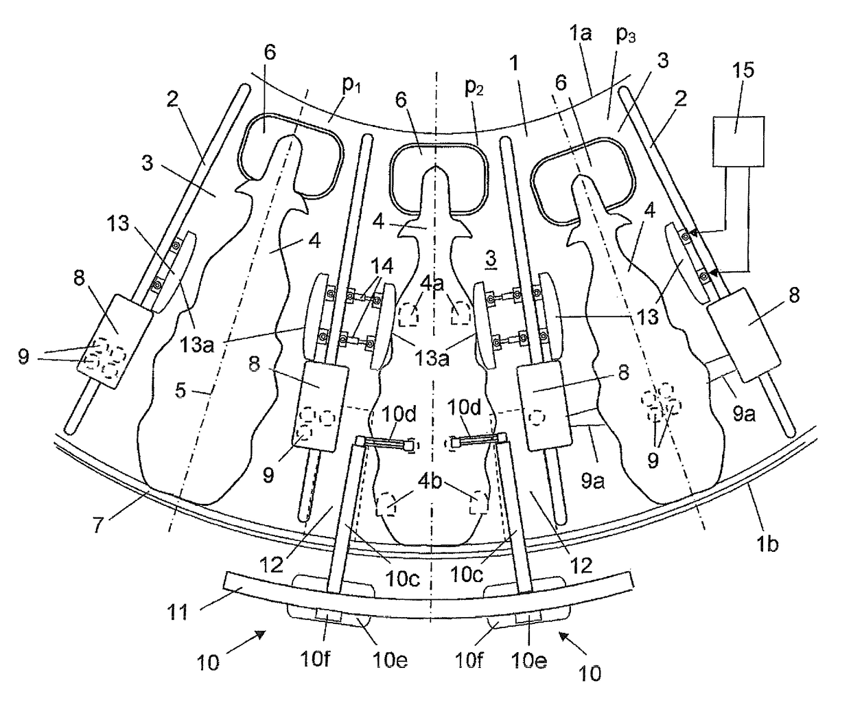
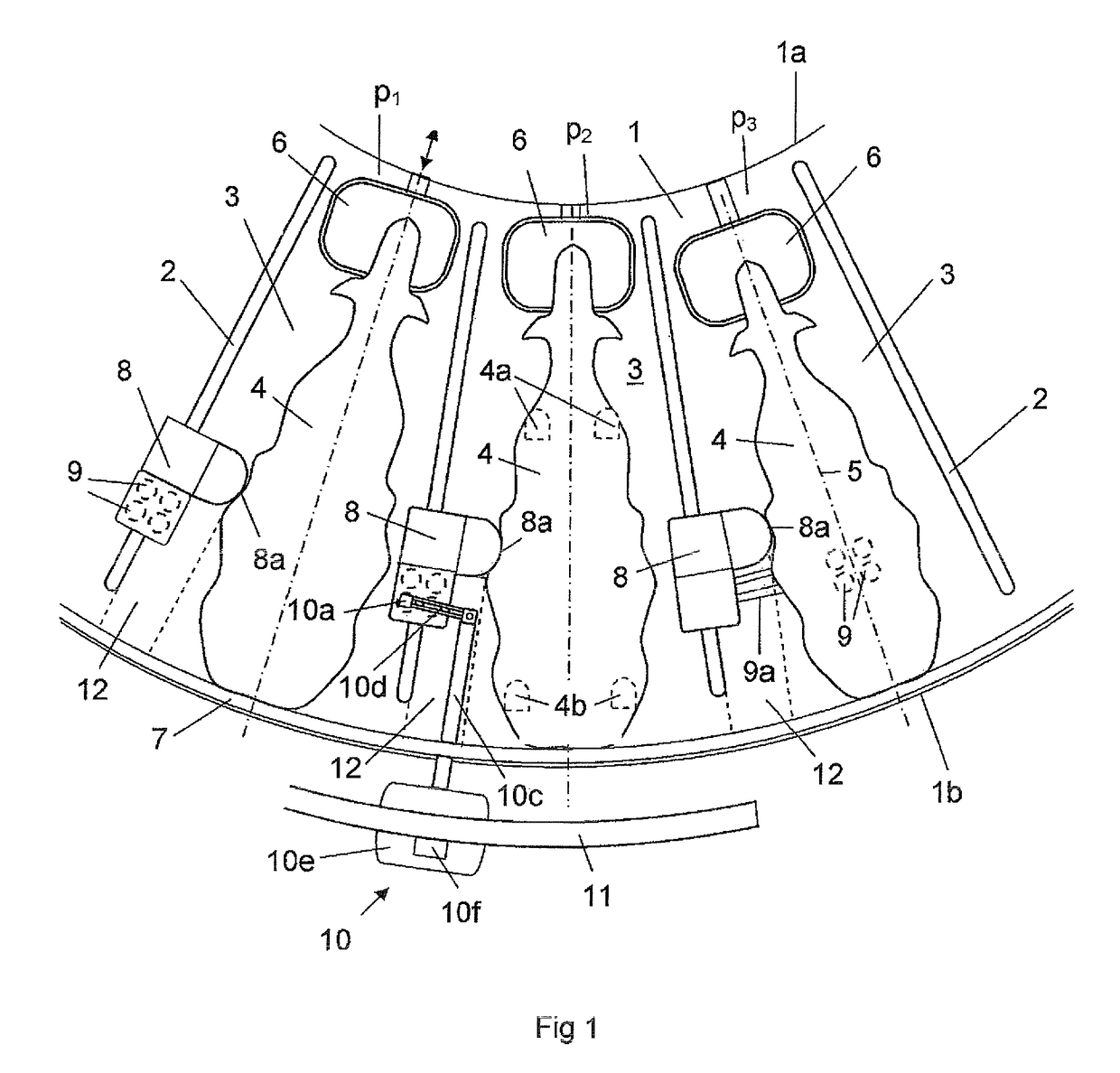
[0025]FIG. 1 shows a part of an annular rotary platform 1. The platform 1 is provided with a plurality of side wall elements 2 each having a substantially radial extension on the platform 1. The side wall elements 2 divide the annular platform into a plurality of milking stalls. FIG. 1 shows three of the milking stalls 3 on the rotary platform 1. A cow 4 is standing in the respective milking stall 3. The positions of the front legs 4a and the rear legs 4b of the cow 4 in one of the milking stalls 3 are indicated. The cows 4 are here standing in a substantially radial direction on the annular platform 1 with the heads at the vicinity of a radial inner edge portion 1a of the platform 1. The longitudinal axes 5 through the cows 4 are indicated.

[0026]Each milking stall 3 comprises a movably arranged feeding trough 6. A rump rail 7 is arranged at a distance above a radial outer edge portion 1b of the platform 1. The rump rail 7 is adapted to define the positions of the rear portions of t...


PUM


Abstract

A rotary parlor arranged to house animals to be milked includes an annular rotary platform (1), at least one milking stall (3) defined by at least one side wall element (2) and a storing device (8) adapted to hold teat cups (9) in a parking position, and a restricting element (8a, 13a, 16a) adapted to restrict the mobility of the animal (4) in the milking stall in a manner such that a free space (12) is created between the animal (4) and a side wall element (2) in a part of the milking stall (3), where the free space (12) is used by a robot arm (10) when fetching a teat cup in the storing device to attach to a teat of the animal (4) in the milking stall (3).

Description

BACKGROUND OF THE INVENTION AND PRIOR ART[0001]The present invention relates to a rotary parlour arranged to house animals to be milked, wherein the parlour comprises an annular rotary platform, at least one milking stall on the platform defined by at least one side wall element having a substantially radial extension on the platform and a storing device adapted to hold teat cups in a parking position.[0002]In a conventional parallel rotary parlour, the cows walk on to an annular rotating platform and enter a milking stall. An operator attaches teat cups to the teats of the cows. The platform may rotate continuously with a constant low speed. The milking processes of the cows has been finished when the cows has rotated nearly 360 degrees on the platform. The continuous flow of cows makes that rotary parlours have a high milking capacity. A condition for a well working milking parlour is the existence of the operator that manually attaches the teat cups to the cows. However, it is de...

Claims


Application Information

Patent Timeline
Patent Type & Authority Patents(United States)
IPC IPC(8): A01K1/12
CPCA01K1/126A01K1/12
Inventor ERIKSSON, JAN
Owner DELAVAL HLDG AB
Why Eureka
Try Eureka