
Movement lock for a locking element or an actuator in a locking system

a technology of moving lock and locking element, which is applied in the direction of cylinder locks, non-mechanical controls, lock applications, etc., can solve the problems that the function that should be realized for example during blocking a rotation or movement is no longer effectiv

Inactive Publication Date: 2017-06-20
ASSA ABLOY SICHERHEITSTECHN
View PDF20 Cites 4 Cited by
  • Summary
  • Abstract
  • Description
  • Claims
  • Application Information

AI Technical Summary

Benefits of technology

The invention aims to prevent unintended movements of locking elements or actuators. This is particularly useful in situations where the movement lock is intended to temporarily block the rotation of an actuator with multiple components. The invention includes a locking bar that engages with a lock cylinder to prevent rotation of the cylinder core when a key has the wrong encoding. The movement lock can also be used to prevent unauthorized access to the locking system using an electrically-operated rotary lock. The invention also includes a reset frame that prevents free rotation of the rotor shaft and a cylinder housing that prevents the locking bar from being disengaged without permission. Overall, the invention provides a secure way to prevent unauthorized movement of locking elements or actuators.

Problems solved by technology

This is based on the supposition that each component has, of course, a certain mass, which may potentially be caused to move as a result of physical energy in the locking system, like vibrations or an external pulse application, so that the function that should be realized for example during blocking of a rotation or movement, is no longer effective.

Method used


Image

  • Movement lock for a locking element or an actuator in a locking system
  • Movement lock for a locking element or an actuator in a locking system
  • Movement lock for a locking element or an actuator in a locking system

Examples


Embodiment Construction

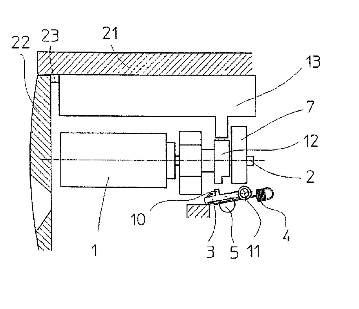
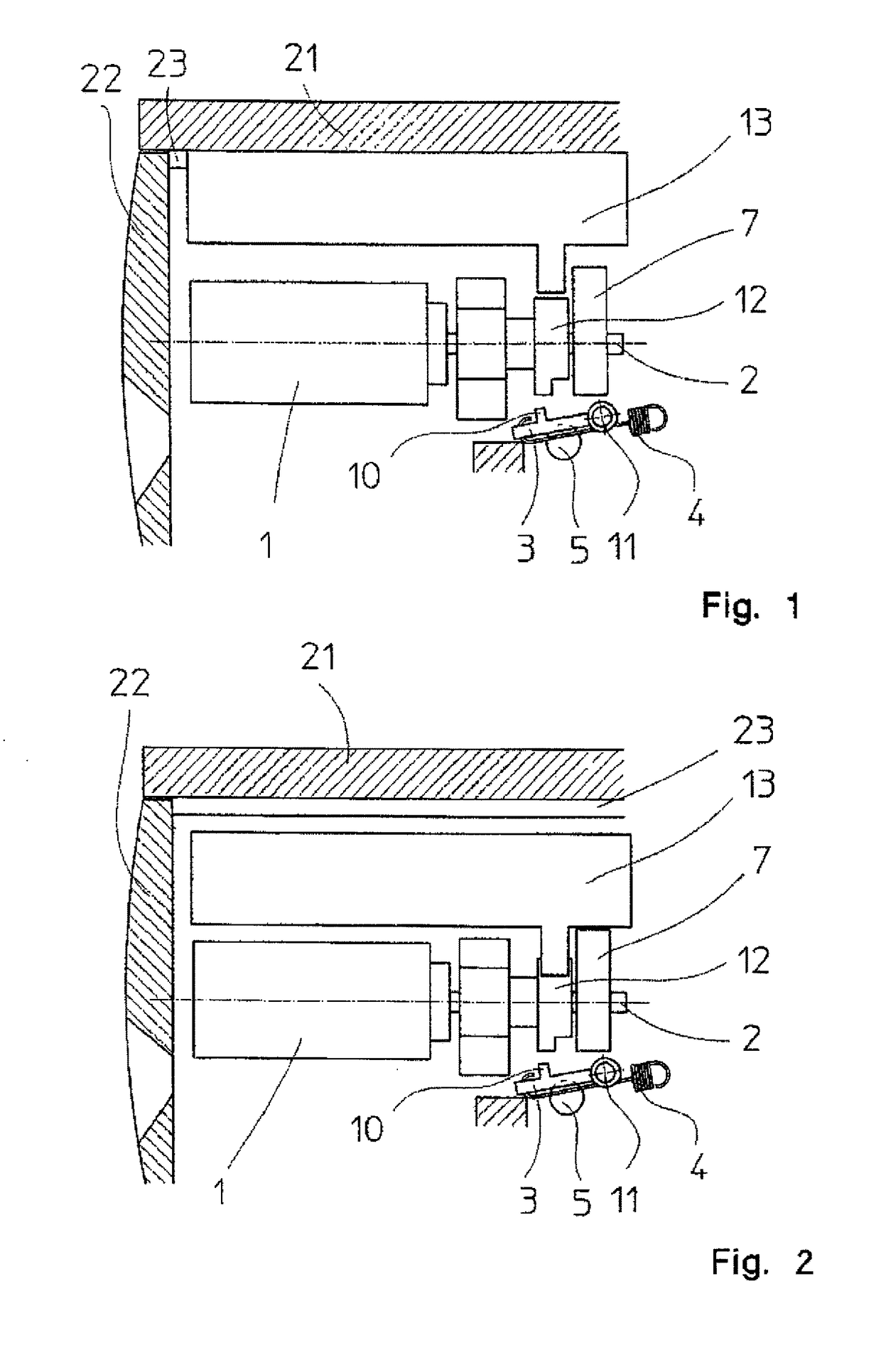
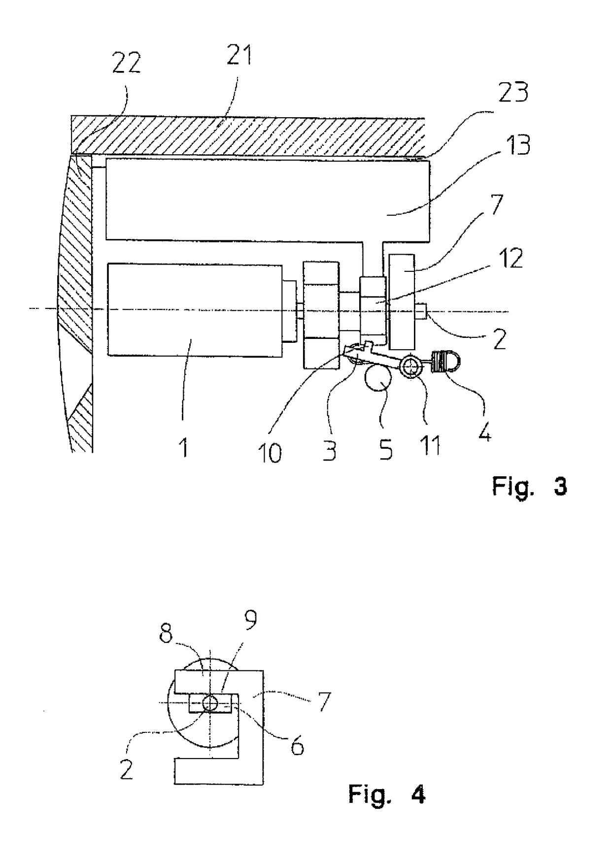
[0025]In a locking system, not shown in detail, an electrically driven actuator 1 is provided for example in a lock cylinder housing 21 in which a cylinder core 22 is rotatably arranged, in which a not shown key can be inserted.

[0026]When an electronically encoded key is used in this locking system, an electrical signal to the actuator is transmitted in the presence of a matching key to cause the rotor shaft 2 to rotate into a position in which the locking bar 13 is released so that the latter is able to move radially inwardly, to emerge from the recess 23, and thus to clear the parting plane between the lock cylinder housing and cylinder core in a customary manner, thereby executing a locking process.

[0027]Vibrations or in particular an external pulse, for example a blow, could cause a slight rotary motion of the rotor shaft, even though the actuator is deactivated in the absence of a matching key.

[0028]In the worst case scenario, this may be sufficient to also liberate the locking...


PUM


Abstract

The invention relates to a movement lock for a locking element or an actuator in a locking system which can be operated in a mechanical or mechatronic manner. Provision is made here for the movement lock to have a blocking element which can be brought into engagement with the locking element or actuator by a system which is maintained under tension or caused to move and can be triggered as a result of an external pulse application on the locking system.

Description

CROSS-REFERENCES TO RELATED APPLICATIONS[0001]This application is the U.S. National Stage of International Application No. PCT / DE2011 / 002057, filed Nov. 23, 2011, which designated the United States and has been published as International Publication No. WO 2012 / 072066 and which claims the priority of German Patent Application, Serial No. 10 2010 053 154.5, filed Nov. 26, 2010, pursuant to 35 U.S.C. 119(a)-(d).BACKGROUND OF THE INVENTION[0002]The invention relates to a movement lock for a locking element or an actuator in a locking system.[0003]Lock cylinders, which not only have a mechanical structure, oftentimes include actuators that affect certain adjustment or blocking members within the lock cylinder and interact with these. This can, for example, involve a rotation or displacement of a component, such as a locking bar or a locking function to prevent rotation or displacement of the component.[0004]This is based on the supposition that each component has, of course, a certain m...

Claims


Application Information

Patent Timeline
IPC IPC(8): E05B47/06E05B33/00E05B49/00E05B17/20E05B15/04
CPCE05B33/00E05B17/2092E05B47/0611E05B49/00E05B2015/0493Y10T70/70Y10T70/7062E05B15/04E05B17/20E05B47/06
Inventor PINTAR, ZELJKOFISCHER, ULRICHLOEB-ULLMANN, CHRISTOPHER
Owner ASSA ABLOY SICHERHEITSTECHN
Learn More