
Method and device for monitoring a drive of a motor vehicle

a technology for monitoring the drive and motor vehicles, applied in the direction of control devices, driver input parameters, vehicle components, etc., can solve the problems of undesired operating constraints and complex sole design, and achieve the effect of more robust and safer

Active Publication Date: 2017-06-27
ROBERT BOSCH GMBH
View PDF32 Cites 1 Cited by
  • Summary
  • Abstract
  • Description
  • Claims
  • Application Information

AI Technical Summary

Benefits of technology

[0009]the permissibility of the operating state of the drive being monitored with the aid of alternative monitoring instead of acceleration monitoring when the operating state of the drive meets at least one predetermined condition, then this has the advantage that the method for monitoring is more robust and safer than sole acceleration monitoring.
[0010]It has been found that the robustness of monitoring which is carried out solely as acceleration monitoring may thus be considerably increased in certain operating states of the drive. It is complex to devise sole acceleration monitoring in such a way that in particular inadvertent accelerations may be reliably and quickly detected in all operating states, without resulting in undesired operating constraints. Such operating constraints may be, e.g., the deactivation of the drive train when it is not possible to safely preclude that an inadvertent acceleration takes place.
[0016]preventing injections of an internal combustion engine when the actual rotational speed is greater than the permissible engine speed.
[0018]Using such rotational speed monitoring as alternative monitoring to acceleration monitoring has the advantage that it is considerably easier to implement than, e.g., torque monitoring, and that it is reliable in the operating states in which it takes the most complexity, or is possible only with difficulty, to ensure the reliability and robustness of sole acceleration monitoring.
[0019]Compared to sole rotational speed monitoring, the described method in contrast has the advantage that the drivability is improved. Moreover, the described method does not require constant involvement of the driver for error detection, and also does not result in any emission-relevant constraints, since, e.g., injections for heating the catalytic converter may also be possible above the permissible engine speed.
[0020]It is particularly advantageous to make the permissible engine speed dependent on the position of the gas pedal. The effects of the rotational speed limitation are thus more comfortable for the driver.

Problems solved by technology

It is complex to devise sole acceleration monitoring in such a way that in particular inadvertent accelerations may be reliably and quickly detected in all operating states, without resulting in undesired operating constraints.
Such operating constraints may be, e.g., the deactivation of the drive train when it is not possible to safely preclude that an inadvertent acceleration takes place.

Method used


Image

  • Method and device for monitoring a drive of a motor vehicle
  • Method and device for monitoring a drive of a motor vehicle
  • Method and device for monitoring a drive of a motor vehicle

Examples


Embodiment Construction

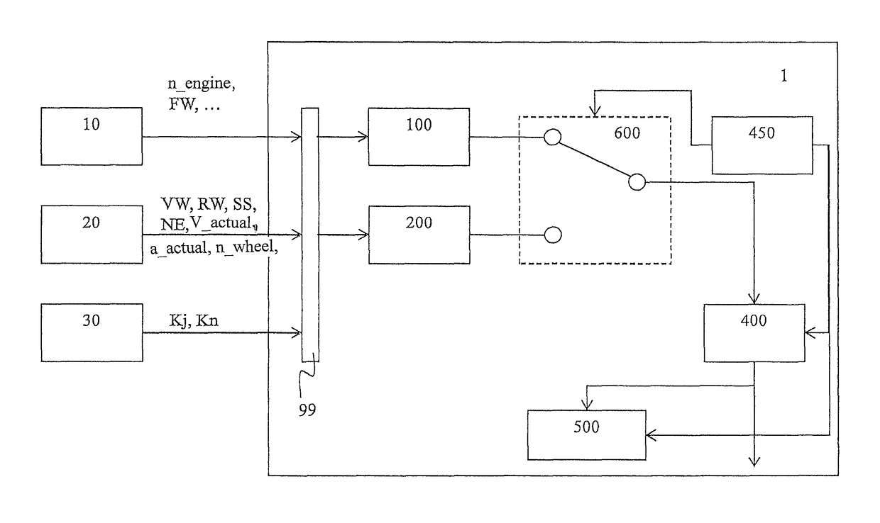
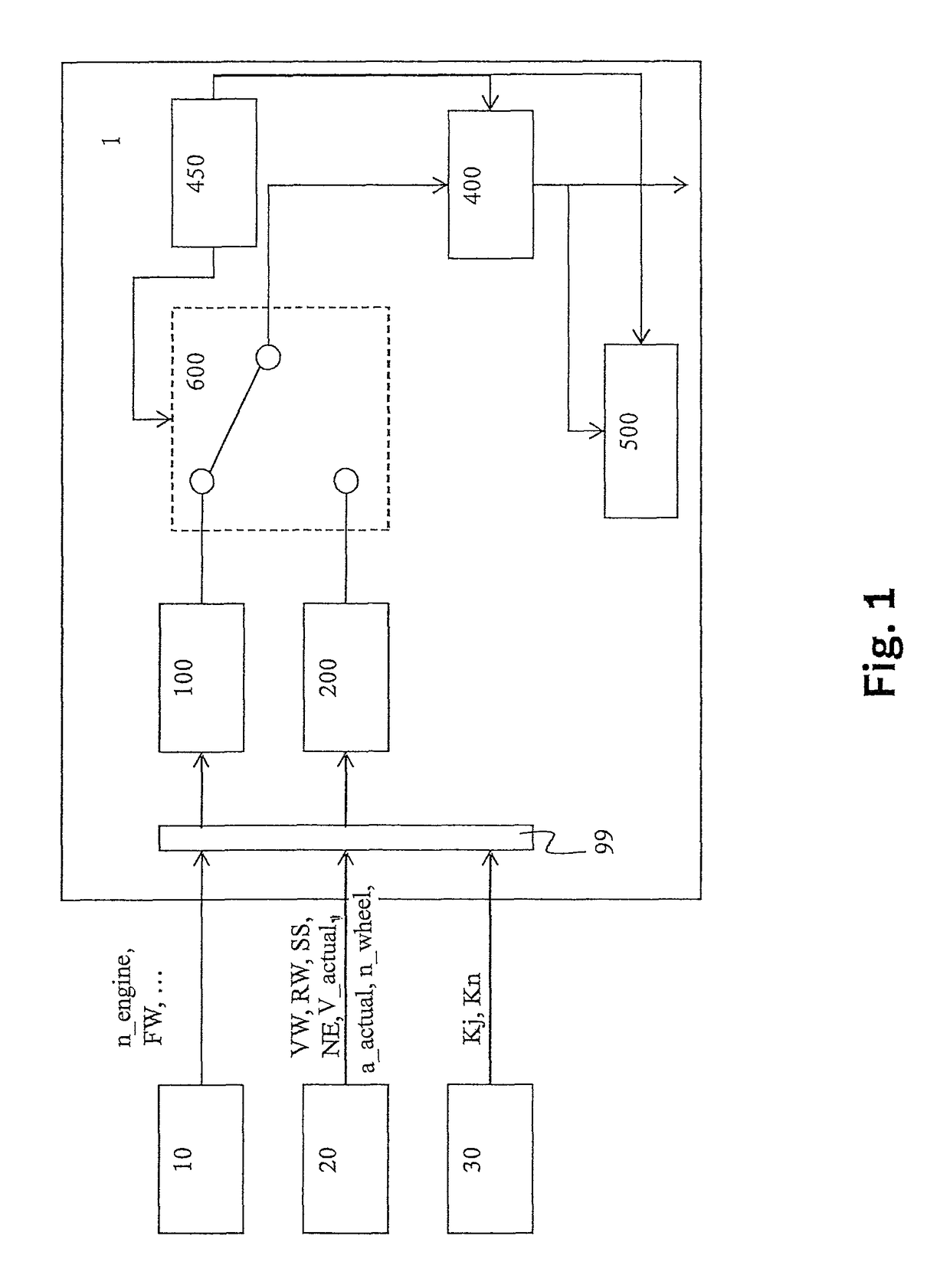
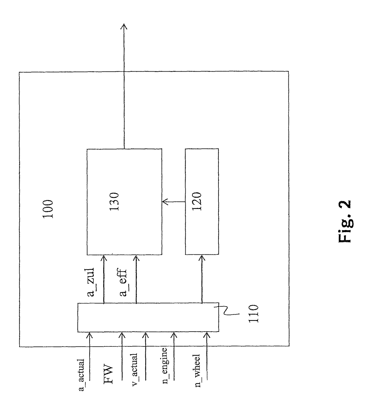
[0049]FIG. 1 schematically shows the configuration of a device which is able to carry out the monitoring method. FIG. 1 shows a control unit 1, e.g., an engine control unit, which controls an engine of the motor vehicle. Control unit 1 receives data from external devices via an interface 99. For example, sensors installed in a drive train 10 transmit rotational speed n_engine of a crankshaft of the engine (instead of rotational speed n of the crankshaft, it is also possible to use another rotational speed characterizing the actual rotational speed of the engine, e.g., a rotational speed of a camshaft) and / or rotational speed n_wheel of one wheel or multiple wheels of the motor vehicle and / or an actual velocity v_actual of the motor vehicle and / or actual acceleration a_actual of the motor vehicle and / or driver input FW ascertained from an actuating degree of the gas pedal, which is usually normalized to values between 0 (gas pedal not actuated) and 1 (gas pedal fully actuated).

[0050]...


PUM


Abstract

A method for monitoring a drive of a motor vehicle, including acceleration monitoring, including: ascertaining an actual acceleration of the motor vehicle with the aid of a signal of a kinematics sensor, in particular of an acceleration sensor or of a wheel speed sensor, ascertaining a permissible acceleration of the motor vehicle as a function of a position of a gas pedal, and ascertaining the permissibility of an operating state of the drive as a function of the ascertained actual acceleration and the ascertained permissible acceleration, the permissibility of the operating state of the drive being monitored with the aid of alternative monitoring instead of acceleration monitoring when the operating state of the drive meets at least one predetermined condition.

Description

RELATED APPLICATION INFORMATION[0001]The present application claims priority to and the benefit of German patent application no. 10 2013 218 554.5, which was filed in Germany on Sep. 17, 2013, the disclosure of which is incorporated herein by reference.FIELD OF THE INVENTION[0002]The present invention relates to a method for monitoring a drive of a motor vehicle. In further aspects, the present invention relates to a computer program for carrying out this method, to an electric memory medium, and to a control unit.BACKGROUND INFORMATION[0003]An acceleration-based method for monitoring the safety of a drive is discussed in DE 10 2011 075 609 A1. Here, a setpoint torque is calculated in a safety function as a function of a gas pedal signal characteristic of the position of the gas pedal. An expected vehicle acceleration is determined in the safety function as a function of the setpoint torque. Moreover, an actual vehicle acceleration is determined, for example, with the aid of an acce...

Claims


Application Information

Patent Timeline
Patent Type & Authority Patents(United States)
IPC IPC(8): B60W50/02
CPCB60W50/0205B60W2520/105B60W2540/10
Inventor PONGRACZ, GABORKOVAC, DALIBORSCHUELER, MATTHIAS
Owner ROBERT BOSCH GMBH
Learn More