
Tool holder

Inactive Publication Date: 2009-08-27
IGEMS SOFTWARE
View PDF8 Cites 4 Cited by
  • Summary
  • Abstract
  • Description
  • Claims
  • Application Information

AI Technical Summary

Benefits of technology

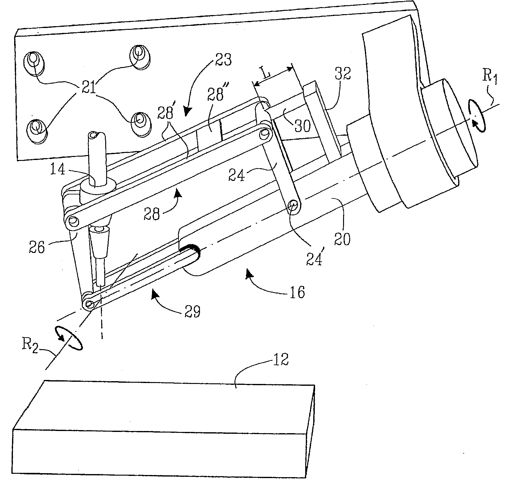
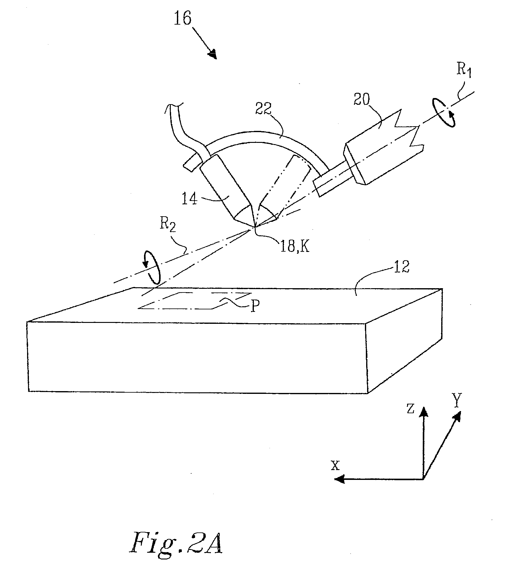
[0009]A second object of the present invention is to provide a tool holder which may tilt a tool around at least two axes of rotation without having any limitation in the rotation.
[0026]In a further embodiment of the present invention, the slewing bracket arrangement comprises a plurality of slewing brackets. When the slewing bracket arrangement comprises a plurality of slewing brackets, a robust and safe tool holder is obtained.

Problems solved by technology

However, there are some disadvantages with the tool holder according to WO 2005 / 035183 A2.
Among others, the tool holder only allows small tilt deflections of the tool and it may furthermore be difficult and costly to obtain a tool holder which provides appropriate tolerances of the tilt of the tool since this makes great demands upon the design of the sphere.
Furthermore, the tool holder according to WO 2005 / 035183 A2 may be sensitive to dirt and working spills and it may be difficult to change tool in the tool holder.
Further, the hemispherical design of the tool holder results in that it may be difficult to find a horizontal neutral position for the tool since the hemisphere covers the tool, and also that this results in a limitation of space for the tool, that is it may be difficult to work an area which is for example close to walls since the tool holder would then hit the wall a long time before the tool reaches the wall.
The location of such a height sensor is made difficult by the above-mentioned design of the tool holder.

Method used


Image

  • Tool holder
  • Tool holder
  • Tool holder

Examples


Embodiment Construction

[0047]The invention will be described by means of examples of embodiments. However, it should be realized that these embodiments only serve the purpose to clarify the present invention, whose scope of protection is limited by the appended claims.

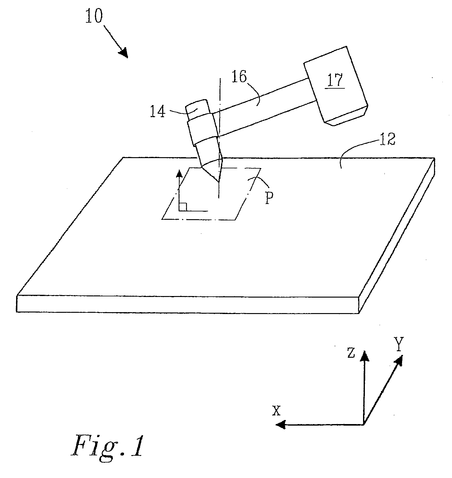
[0048]FIG. 1 illustrates a converting system 10 according to the invention for working a work piece 12 with a tool 14. At least a portion of the work piece 12 extends substantially in a plane P, which plane in the example illustrated in FIG. 1 extends along an X and a Y dimension. In FIG. 1, the whole work piece 12 extends in the plane P. The tool 14 maybe of various kinds, for example the tool 14 may be a cutting tool which utilizes for instance plasma cutting, laser cutting or water cutting. In the case of water cutting, the tool may preferably be connected to a high pressure pump (not shown) adapted to generate a water pressure, which flows through a nozzle of the tool.

[0049]In the case of a water cutting tool, this may also comprise mean...


PUM

PropertyMeasurementUnit
Distanceaaaaaaaaaa

Abstract

The present invention relates to a tool holder, adapted to hold a tool for working at least a portion of a work piece, which portion extends substantially in a plane. The tool has a working tip which is located in an apex position of the tool holder when the tool holder holds the tool. The tool holder comprises an arm which is pivotable around a first axis of rotation and a fastening device adapted to carry the tool. The fastening device is connected to the arm and the tool is pivotable around a second axis of rotation when the fastening device carries the tool.

Description

PRIORITY INFORMATION[0001]The present application claims priority to Swedish Application Serial No. SE0800438-4, filed on Feb. 25, 2008, which is incorporated herein by reference in its entirety.TECHNICAL FIELD[0002]The present invention relates to a tool holder, adapted to hold a tool for working at least a portion of a work piece, which portion extends substantially in a plane. The tool has a working tip which is located in an apex position of the tool holder when the tool holder holds the tool. The tool holder comprises an arm which is pivotable around a first axis of rotation and a fastening device adapted to carry the tool. The fastening device is connected to the arm and the tool is pivotable around a second axis of rotation when the fastening device carries the tool.BACKGROUND OF THE INVENTION[0003]When working a work piece, in particular when working by cutting, a working tool is often used which is conducted over the work piece. This working tool is usually attached to an a...

Claims


Application Information

Patent Timeline
IPC IPC(8): B23B31/36
CPCB23K26/0861B23K26/0876B23K26/38Y10T279/13B23Q1/54B26D7/2628B26F3/004B23K37/0211
Inventor JOHANSSON, BO GORAN
Owner IGEMS SOFTWARE
Learn More