
Light emitting device

a technology of light-emitting devices and light-emitting components, which is applied in the direction of semiconductor lasers, lighting and heating apparatus, instruments, etc., can solve the problems of moving parts, reliability and/or safety risks, wear and tear, etc., and achieves improved reliability and efficiency, simple construction, and more robust and safe

Active Publication Date: 2020-03-31
SIGNIFY HLDG BV
View PDF19 Cites 0 Cited by
  • Summary
  • Abstract
  • Description
  • Claims
  • Application Information

AI Technical Summary

Benefits of technology

The present invention aims to provide a light emitting device that can avoid overheating of the luminescent element, improve reliability and efficiency, and is more versatile, simpler, robust, safe, and cost-efficient to manufacture. Additionally, the light output of the device has a suitable etendue.

Problems solved by technology

This has several drawbacks, including:The system includes moving parts that may wear out and are sensitive to failure.
When the rotation of the wheel fails, the cooling function is lost and the device will fail, posing a reliability and / or safety risk.Moving parts cannot be allowed in all applications, for instance in applications with moving lamps, such as entertainment lamp / gobo projectors, to prevent gyroscopic effects.The phosphor wheel increases the size of the system.
A common wheel size has a diameter of 3-4 cm.It is difficult to add extraction optics to the phosphor layer, limiting efficiency within a small spot size.The phosphor is not restricted along the rotation direction which increases the spot size due to light spreading within the phosphor.
This increases the etendue.A phosphor wheel is an expensive component to make.
A 100$ wheel cost is not uncommon.Phosphor wheels are furthermore sensitive in reliability, prone to degradation.
This is due to limited heat sinking capability and photo-thermal degradation sensitivity of the phosphor coated.
An improvement can be made by using a ceramic phosphor on the phosphor wheel instead of a coating of a powder phosphor in a binder, but this is known to be a quite costly approach.
Hence a too large source etendue may generate a lot of light, but this cannot be harvest by the optical system of the projector.
A too small source etendue can put unnecessarily high thermal loads to the source and limit the optical efficiency.

Method used


Image

  • Light emitting device
  • Light emitting device
  • Light emitting device

Examples


example —

Example—Measurements

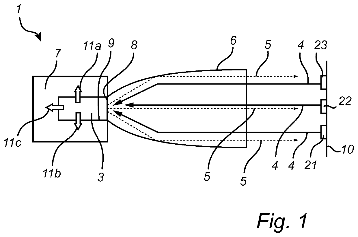
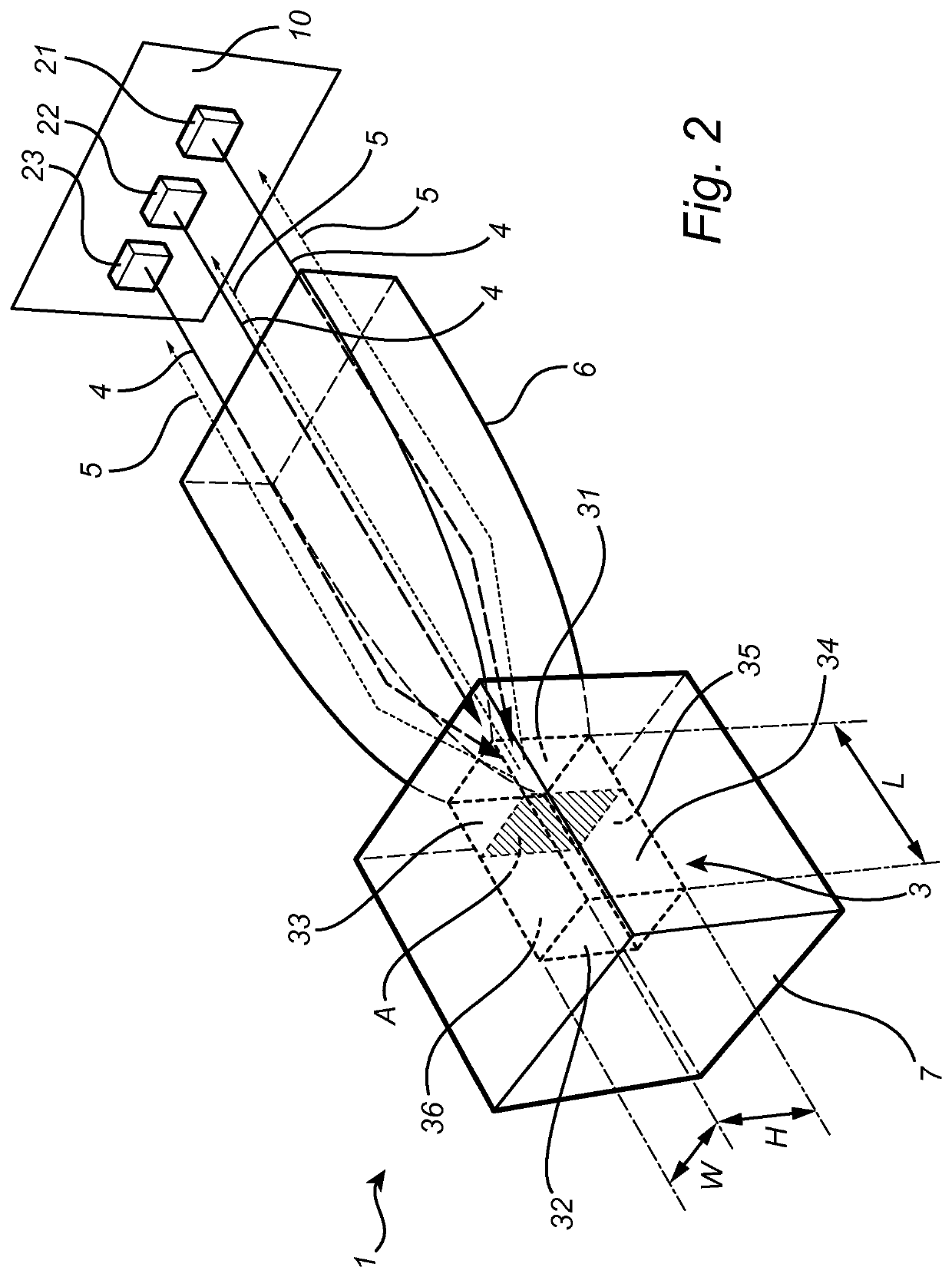
[0114]FIGS. 5 to 13 illustrate optical simulations made on an exemplary light emitting device according to the invention. The optical ray-trace simulations were made on a light emitting device 1 of the type shown in FIGS. 1 and 2 and comprising a rectangular rod-shaped luminescent element 3 with a heat sink element 7 on five faces 32, 33, 34, 35, 36 and, as a focusing optical element 6, a glass compound parabolic concentrator (CPC) attached to the first face 31. The configuration was modeled in reflective mode, that is, the CPC is used both for injecting the laser light 4 and for extracting the converted light 5 from the luminescent element. The luminescent element 3 used was a YAG ceramic luminescent element. The laser light 4 injected into the luminescent element 3 was blue and the converted light 5 green or yellow.

[0115]First, the heat load in the YAG ceramic luminescent element was determined by the conversion, i.e. absorption of blue light. The blue light ab...


PUM

PropertyMeasurementUnit
refractive indexaaaaaaaaaa

Abstract

A light emitting device (1) comprising a luminescent element (3) comprising a first face (31) and a second face (32), the first face comprising a light input surface and one of the first face and the second face comprising a light exit surface, the luminescent element (3) being adapted for receiving first light (4) with a first spectral distribution emitted by at least one laser light source (21, 22, 23) at the light input surface, converting at least a part of the first light with the first spectral distribution to second light (5) with a second spectral distribution, guiding the second light with the second spectral distribution to the light exit surface and coupling at least a part of the second light with the second spectral distribution out of the light exit surface, and a heat sink element (7) arranged to be in thermal contact with at least a part of the luminescent element (3) extending between the first face (31) and the second face (32), wherein the first face (31) comprises a cross-sectional area A and the luminescent element (3) further comprises a length L being defined as the shortest distance between the first face and the second face and a characteristic length B of the cross sectional area A, the characteristic length B being defined as the square root of the cross sectional area A, and wherein, and wherein the length L and the characteristic length B of the cross sectional area A are chosen such that they satisfy any one of the relations L / B≥2*Ells / 44(W / mm2) for λTHC<6 W / mK, L / B≥1.3*Ells / 44(W / mm2) for 6 W / mK≤λTHC≤8 W / mK, and L / B≥0.85*Ells / 44(W / mm2) for 8 W / mK<λTHC, where Ells is the irradiance of the at least one laser light sources measured in W / mm2 and λTHC is the thermal heat coefficient of the luminescent element at room temperature.

Description

CROSS-REFERENCE TO PRIOR APPLICATIONS[0001]This application is the U.S. National Phase application under 35 U.S.C. § 371 of International Application No. PCT / EP2017 / 055136, filed on Mar. 6, 2017, which claims the benefit of European Patent Application No. 16160318.8, filed on Mar. 15, 2016. These applications are hereby incorporated by reference herein.FIELD OF THE INVENTION[0002]The invention relates to a light emitting device comprising a luminescent element comprising a first face and a second face, the first face comprising a light input surface and one of the first face and the second face comprising a light exit surface, the luminescent element being adapted for receiving first light with a first spectral distribution emitted by at least one laser light source at the light input surface, converting at least a part of the first light with the first spectral distribution to second light with a second spectral distribution, guiding the second light with the second spectral distri...

Claims


Application Information

Patent Timeline
Patent Type & Authority Patents(United States)
IPC IPC(8): G03B21/20F21S41/16F21V9/30F21K9/64F21V29/502F21V29/70H01S5/323G03B21/16F21V7/00F21V5/00F21V7/22H01S5/40F21S41/20F21S41/176H01S5/00F21Y101/00
CPCG03B21/204H01S5/005G03B21/2066F21S41/285F21V9/30F21V29/70F21K9/64F21S41/176F21V29/502F21S41/16G03B21/16F21Y2101/00H01S5/4025F21V7/0091F21V7/22H01S5/32341F21V5/00F21V13/14F21V7/28H01S5/0087H01S5/0225
Inventor JAGT, HENDRIK JOHANNES BOUDEWIJNBRULS, DOMINIQUE MARIABENOY, DANIËL ANTONDE BOER, DIRK KORNELIS GERHARDUSCORNELISSEN, HUGO JOHANVREHEN, JORIS JANBOEREKAMP, JACOBUS GERARDUSHOELEN, CHRISTOPH GERARD AUGUST
Owner SIGNIFY HLDG BV
Learn More