Conveyor unit and conveyor system for conveying vehicle bodies and plant for machining vehicle bodies

a conveyor system and vehicle body technology, applied in the direction of vehicles, mechanical conveyors, spraying apparatus, etc., can solve the problems of increasing the total cost of such a treatment plant, and achieve the effect of reducing the number of skids and ensuring the space occupied by unladen conveyor units

Active Publication Date: 2017-06-27
EISENMANN GMBH
View PDF21 Cites 9 Cited by
  • Summary
  • Abstract
  • Description
  • Claims
  • Application Information

AI Technical Summary

Benefits of technology

[0010]According to the invention, the conveyor unit therefore acts directly on a vehicle body without this latter having to be secured to a skid for transportation. It is therefore possible to reduce the number of skids required, since a certain number of skids only have to be provided for the treatment stations in which the vehicle body needs to be secured to a skid. It is also possible to dispense with skids completely, at least in individual treatment zones or regions thereof, as long as the type of treatment permits this.
[0011]It is favourable if the coupling device comprises a plurality of coupling elements which can be moved between a load-carrying position and an idle position. In their load-carrying position here, the coupling elements preferably project beyond the clear outer contour of the conveyor unit as seen from above and, in the idle position, are located within the lateral clear outer contour of the conveyor unit as seen from above, i.e. within the delimitation of the conveyor unit to the right and left with respect to its direction of travel. Therefore, the space occupied by unladen conveyor units can be kept small. Moreover, conveyor units with their coupling elements in their idle position can be moved towards other conveyor systems in space-saving manner and can receive a vehicle body from the other conveyer systems there after the coupling elements have been brought into their load-carrying position.

Problems solved by technology

This increases the total cost of such a treatment plant.

Method used


Image

  • Conveyor unit and conveyor system for conveying vehicle bodies and plant for machining vehicle bodies
  • Conveyor unit and conveyor system for conveying vehicle bodies and plant for machining vehicle bodies
  • Conveyor unit and conveyor system for conveying vehicle bodies and plant for machining vehicle bodies

Examples


Embodiment Construction

[0032]While this invention is susceptible of embodiment in many different forms, there is shown in the drawings and will herein be described in detail one or more embodiments with the understanding that the present disclosure is to be considered as an exemplification of the principles of the invention and is not intended to limit the invention to the embodiments illustrated.

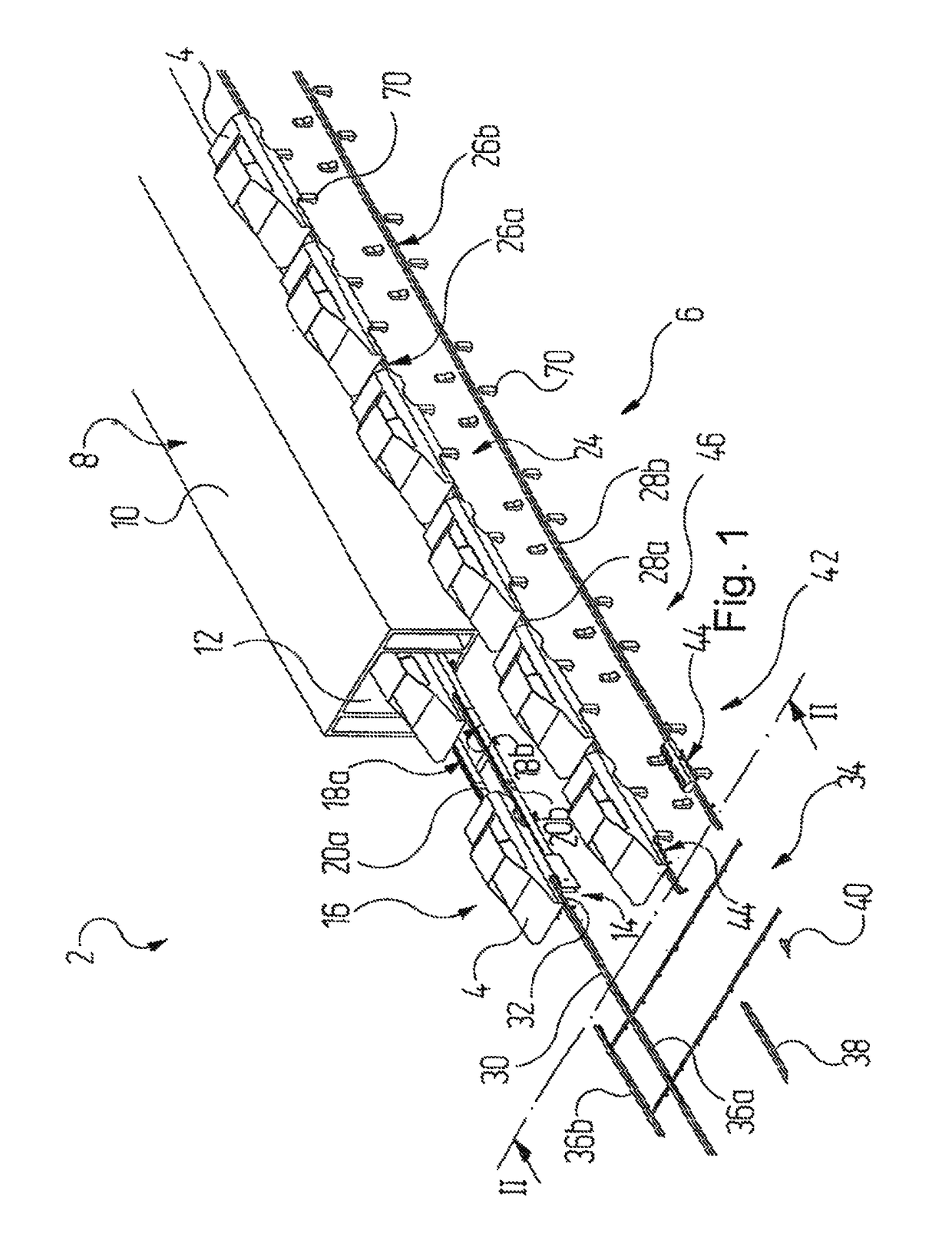
[0033]FIG. 1 shows a sub-region of a plant 2 for treating vehicle bodies 4. In the plant 2, the vehicle bodies 4 are transported between, and sometimes also within, individual treatment stations, such as bodyshell-work, paint and assembly stations, by means of a conveyor system which is denoted as a whole by 6.

[0034]By way of example of a treatment station, FIG. 1 shows a drier 8 having a drier housing 10 which delimits a drying tunnel 12. In the drier 8, paint is dried in a manner known per se on vehicle bodies 4 which have been coated with this paint in a prior operating step in a paint station which is not sho...


PUM


Abstract

A conveyor unit which can be displaced for conveying vehicle bodies and which includes a bogie assembly and a coupling device which is connected to the bogie assembly and which is configured such that it interacts with the base areas of the vehicle body which are upwardly orientated to the roof. Also a conveyor system having at least one conveyor unit of such type and a plant for machining vehicle bodies. Vehicle bodies are conveyed by a conveyor system between and/or in machining stations, said plant also including such a conveyor system.

Description

RELATED APPLICATIONS[0001]This application claims the filing benefit of International Patent Application No. PCT / EP2011 / 004179, filed Aug. 19, 2011, which claims the filing benefit of German Patent Application No. 10 2010 045 010.3 filed Sep. 10, 2010, the contents of both of which are incorporated herein by reference.FIELD OF THE INVENTION[0002]The invention relates to a conveyor unit and a conveyor system for conveying vehicle bodies and a plant for treating vehicle bodies, in which vehicle bodies are conveyed between and / or within treatment stations by means of a conveyor system.BACKGROUND OF THE INVENTION[0003]In addition to a surface treatment, such as cleaning or painting, the term treatment is also used here to refer to any type of process on the vehicle body, for example bodyshell or assembly work.[0004]In commercially known plants for such treatment of vehicle bodies, vehicle bodies to be treated are often conveyed on so-called skids between, and sometimes also in, individu...

Claims


Application Information

Patent Timeline
Patent Type & Authority Patents(United States)
IPC IPC(8): B65G35/06B65G21/22B05B13/02B62D65/18B05B13/04
CPCB65G35/06B05B13/0221B62D65/18B65G21/22B05B13/0452B65G2201/0294
Inventor ROBBIN, JOERG
Owner EISENMANN GMBH
Why Eureka
Try Eureka