Supercharge Your Innovation With Domain-Expert AI Agents!

Hydraulic accumulator

a technology of accumulators and accumulators, applied in the direction of accumulator installations, fluid-pressure actuators, pipe elements, etc., can solve the problems of difficult buckling of self-seal stays, small self-seal stays, etc., to facilitate buckling, reduce the number of steps for fabrication, and simple construction

Active Publication Date: 2017-06-27
NHK SPRING CO LTD
View PDF11 Cites 2 Cited by
  • Summary
  • Abstract
  • Description
  • Claims
  • Application Information

AI Technical Summary

Benefits of technology

The present invention is related to a hydraulic accumulator that includes a first weakened portion. This design feature helps improve productivity and manage dimensional accuracy. The accumulator also has a simple construction, reduces the number of steps for fabrication, and facilitates regulating a relief pressure for releasing the pressure in the gas chamber. Additionally, the accumulator effectively prevents noise and shock from occurring at releasing of the high-pressure gas and regulates the relief pressure of the high-pressure gas.

Problems solved by technology

Especially, downsizing of the hydraulic accumulator makes height of the self-seal stay smaller, which makes it difficult for the self-seal stay to buckle.

Method used


Image

  • Hydraulic accumulator
  • Hydraulic accumulator
  • Hydraulic accumulator

Examples


Embodiment Construction

[0040]The detailed description will be given of a construction of a hydraulic accumulator 1 according to an embodiment of the invention, referring to FIGS. 1 to 5C as necessary.

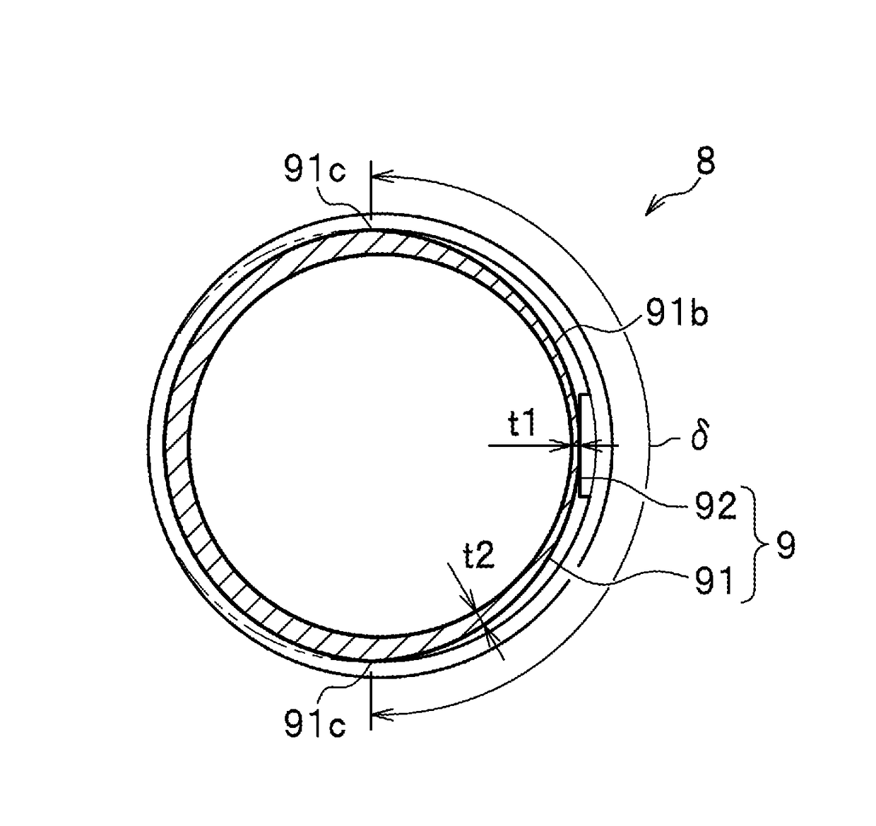
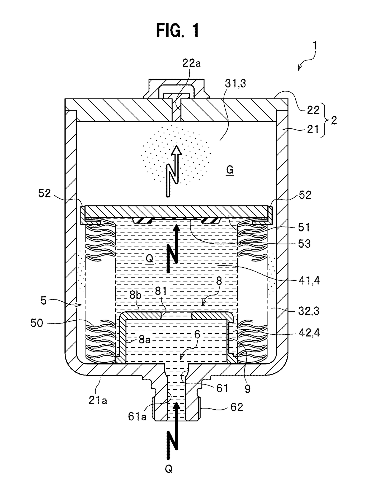
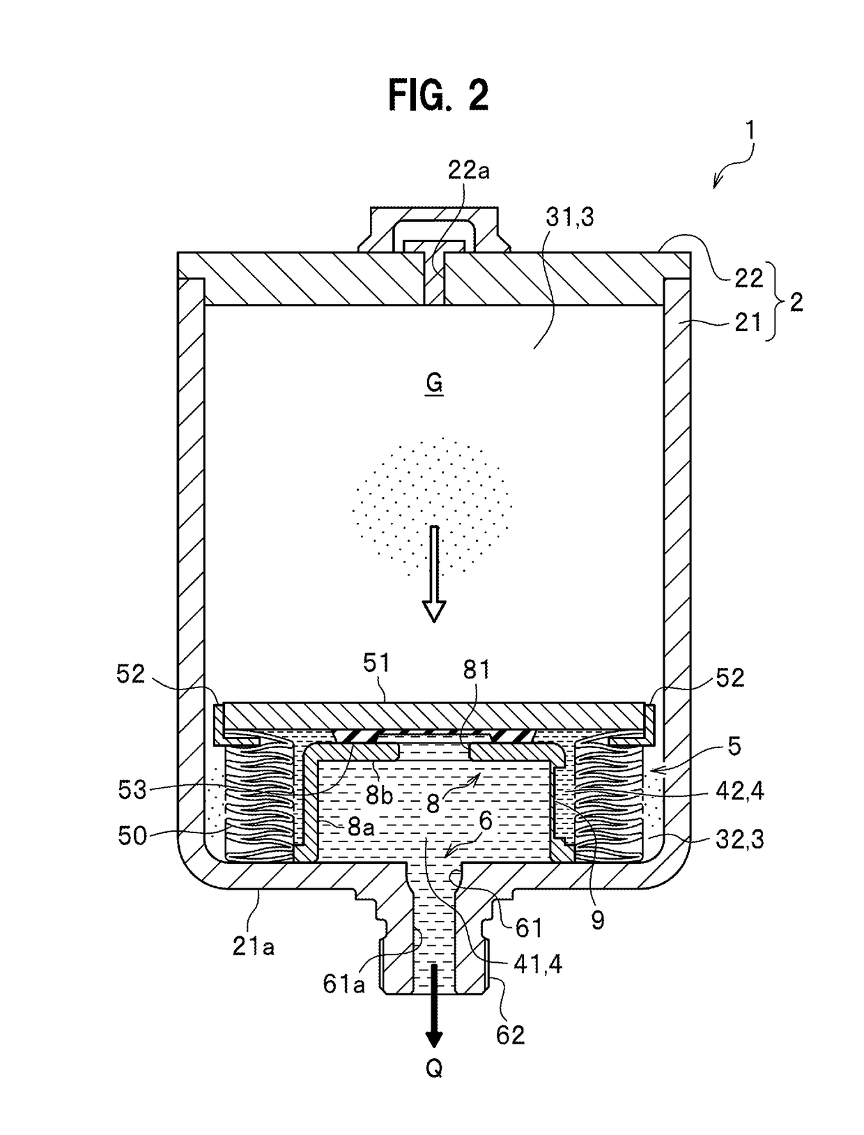
[0041]The hydraulic accumulator, as illustrated in FIG. 1, includes a shell 2 of a pressure container, a gas chamber 3 and a fluid chamber 4 formed inside the shell 2, the gas chamber 3 having a high-pressure gas G sealed therein, the fluid chamber 4 having hydraulic fluid Q introduced from a hydraulic circuit such as a brake circuit not illustrated, a bellows 5 expandably and contractably housed in the shell 2, a port portion 6 of the shell 2 formed with a hydraulic-fluid inlet 61 open to the fluid chamber 4, and a self-seal stay 8 disposed in the fluid chamber 4 and covering the port portion 6.

[0042]The bellows 5 is a partition member which serves as a boundary between the gas chamber 3 and the fluid chamber 4. The bellows 5 includes an expansion-contraction portion 50 formed as bellows, an end portion 51 f...


PUM


Abstract

A hydraulic accumulator includes a shell, a bellows, and a self-seal stay disposed at a hydraulic-fluid inlet and including a cylindrical body portion open to a hydraulic chamber and a lid-shaped head portion defining a through hole. The self-seal stay includes a first weakened portion for deforming the body portion when a pressure of the gas chamber is more than a given threshold. The first weakened portion includes a first recessed portion formed in a circumferential direction of the body portion. The first recessed portion includes a bottom surface of a plane surface or a circular arc shaped curved surface which is convex toward outside of the body portion from inside thereof. At least one of both end portions of the bottom surface in the circumferential direction is joined with an outer circumferential surface of the body portion.

Description

CROSS-REFERENCE TO RELATED APPLICATIONS[0001]This application is based upon Japanese Patent Application No. 2015-028872 filed on Feb. 17, 2016; the entire contents of which are incorporated herein by reference.BACKGROUND OF THE INVENTION[0002]The invention relates to a hydraulic accumulator, and particularly relates to a hydraulic accumulator including a self-seal stay with a weakened portion.[0003]An automobile's brake circuit or the like has a hydraulic circuit, which employs a hydraulic accumulator for temporarily storing fluid increased in pressure. The hydraulic accumulator includes a gas chamber in which a gas of a high pressure is sealed, and a fluid chamber in which a hydraulic fluid (hydraulic oil) is introduced. The gas chamber and the fluid chamber are arranged opposite to each other relative to an expandable and contractable bellows. Expanding and contracting of the bellows makes the pressure of the gas chamber and the pressure of the fluid chamber balance with each othe...

Claims


Application Information

Patent Timeline
IPC IPC(8): F16L55/04F15B1/08
CPCF15B1/08F15B2201/205F15B1/083F15B1/103F15B2201/3153F15B2201/40
Inventor MIZUKAMI, HIROSHI
Owner NHK SPRING CO LTD
Features
  • R&D
  • Intellectual Property
  • Life Sciences
  • Materials
  • Tech Scout
  • Unparalleled Data Quality
  • Higher Quality Content
  • 60% Fewer Hallucinations
Learn More