
Apparatus and method for maintaining patient temperature during a procedure

a technology for maintaining patient temperature and anaesthesia, applied in the field of anaesthesia apparatus and temperature maintenance for patients, can solve problems such as potential hypothermia, and achieve the effect of facilitating maintenance of patient temperatur

Active Publication Date: 2017-07-04
DUNLOP COLIN
View PDF17 Cites 4 Cited by
  • Summary
  • Abstract
  • Description
  • Claims
  • Application Information

AI Technical Summary

Benefits of technology

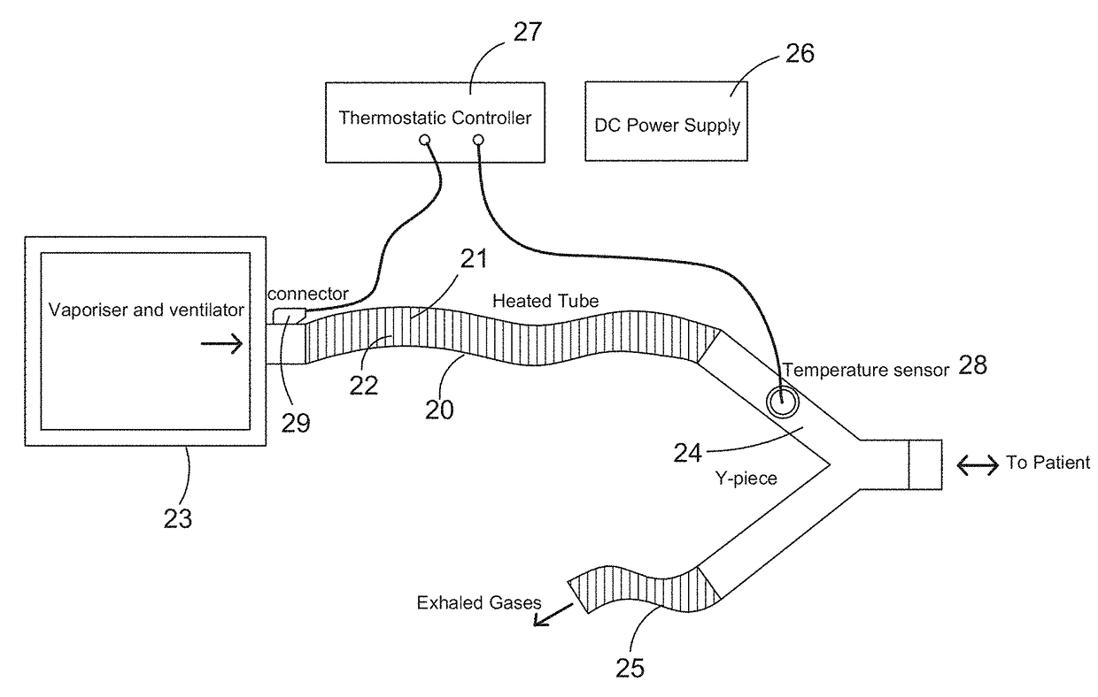
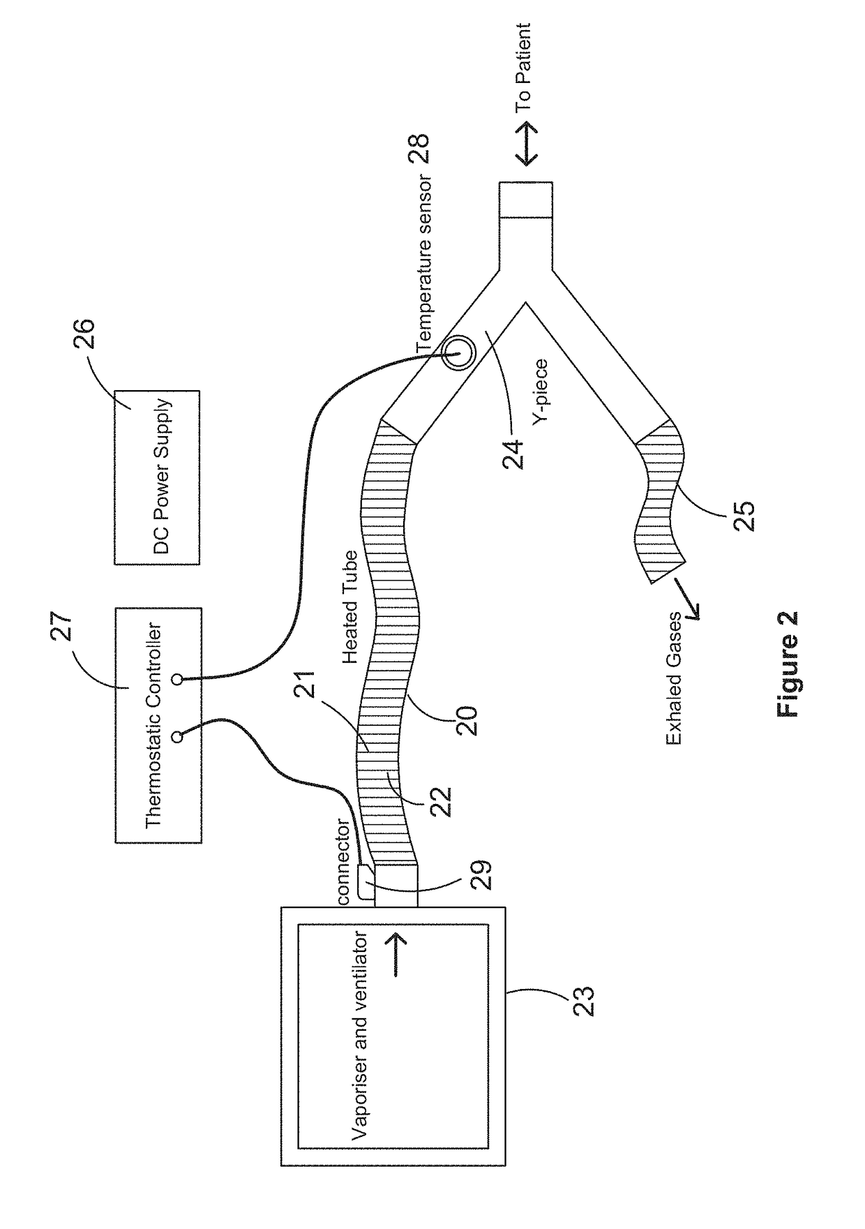
[0006]Advantageously, in at least an embodiment, heating the gas facilitates maintenance of the temperature of the patient, as the patient breaths the heated gas.
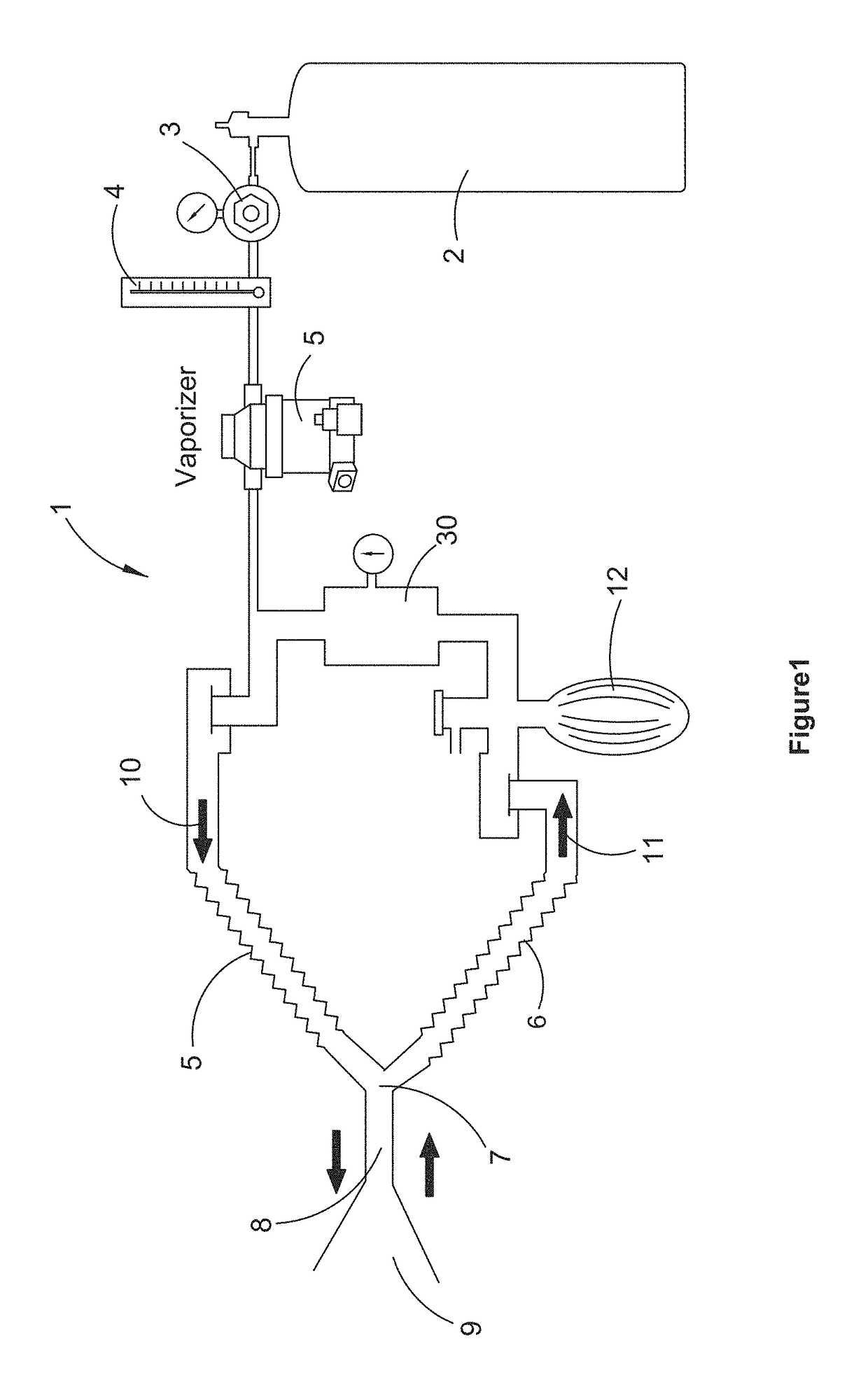
[0007]The present Applicant's have found that, in conventional anaesthesia, where the gas is not heated, the process of breathing the anaesthetic gas (which is usually cool and dry) contributes to cooling of the patient leading to potential hypothermia. Embodiments of the present invention minimise this danger by heating the gas within the anaesthetic apparatus so that the patient is breathing heated gas.
[0012]The Applicant's have found that having smooth wall tubing facilities heating of the gas within the bore of the tubing. They have also found that the smooth wall facilitates flow of the gas along the passageway.
[0015]Conventional tubing used in an anaesthetic apparatus is in the order of 20-25 mm (usually 20-22 mm) in diameter. It has been previously thought that lower passageway diameters may lead to high resistance within the anaesthetic circuit leading to difficulty in the patient breathing. The Applicant's have found, surprisingly, that with smooth walled tubing, lesser diameters than 20 mm can be used without deleteriously increasing the resistance of the anaesthetic circuit and affecting patients breathing. Further, with lower diameter tubing, the Applicant's have found that the gas flowing within the passageway is heated more effectively.

Problems solved by technology

The present Applicant's have found that, in conventional anaesthesia, where the gas is not heated, the process of breathing the anaesthetic gas (which is usually cool and dry) contributes to cooling of the patient leading to potential hypothermia.

Method used


Image

  • Apparatus and method for maintaining patient temperature during a procedure
  • Apparatus and method for maintaining patient temperature during a procedure
  • Apparatus and method for maintaining patient temperature during a procedure

Examples


example

[0102]All hoses were tested as they were produced, connected to standard anaesthetic machine 22 mm Tapered outlets identical to ones found on all soda lime absorbers near the one-way valves.

[0103]10-50 L / min air was delivered from a calibrated flowmeter and passed through the hose while it was flat and straight ensuring no pressure variances due to gravity or a coiled hose. Shown below in the table is the Comparative Breathing Hose Resistance which has not been adjusted for length or for the restriction size from 22 mm. Included in the results in the last column are resistance values of a standard 22 13 mm ID restriction described in the method.

[0104]

COMPARATIVE BREATHING HOSE RESISTANCE (NON ADJUSTED FOR LENGTH)15 mmFlowPastiflex:22 mmClearUniversal:Universal:Rate12 mm16 mm20 mmClearCor.F-F-22-13 mm(L / min)HeatedHeatedHeatedCor.PediatricInspiratoryExpiratoryOrifice100.120.050.020.010.080.090.140.02200.310.080.010.000.250.280.390.02300.830.210.050.010.630.680.850.08401.620.420.100.03...


PUM


Abstract

An apparatus and method for maintaining patient temperature during an anaesthetic procedure. Patients, particularly small patients, can lose body temperature when undergoing surgery or other procedures where they are anaesthetized. The process of breathing the cool anaesthetic gas contributes to the temperature loss of the patient. An anaesthetic apparatus is arranged to warm the gas being provided for the patient to breathe, to facilitate maintaining body temperature. An inspired limb of an anaesthetic circuit comprises tubing with a heating conductor for heating the inspired gas.

Description

CROSS-REFERENCE TO RELATED APPLICATIONS[0001]This application is a continuation of International Application No. PCT / AU2012 / 001103 filed on Sep. 14, 2012, which claims priority to Australian Patent Application No. 2012903900 filed on Sep. 7, 2012 and to Australian Patent Application No. 2011903770 filed on Sep. 14, 2011, the disclosures of which are incorporated herein in their entirety by reference.FIELD OF THE INVENTION[0002]The present invention relates to an apparatus and method for maintaining patient temperature during a medical procedure and, particularly, but not exclusively, to a method and apparatus for maintaining patient temperature during anaesthesia.BACKGROUND OF THE INVENTION[0003]A problem with medical procedures such as, for example, surgery is maintenance of the temperature of the patient.[0004]This is a particular problem for smaller patients, for example, less than 40 kgs. It has been found that for in the order of 85% of small animals (less than 40 kgs, but more...

Claims


Application Information

Patent Timeline
Patent Type & Authority Patents(United States)
IPC IPC(8): A61M11/00A61D7/04A61M16/01A61D99/00A61M16/10A61M16/08A61M16/18A61M16/22
CPCA61D7/04A61D99/00A61M16/01A61M16/0875A61M16/0891A61M16/1075A61M16/1095A61M16/0816A61M16/18A61M16/22A61M2202/0208A61M2205/3368A61M2205/3653A61M2205/502A61M2230/50A61M16/0833A61M2016/003
Inventor DUNLOP, COLIN
Owner DUNLOP COLIN
Learn More