Orthopaedic instrument for securing a bone

a technology for orthopaedic instruments and bone, applied in the field of orthopaedic instruments, can solve the problems of pathologic bone loss at the affected joint, severe pain, time-consuming and difficult, etc., and achieve the effect of avoiding the risk of bone dropping or increasing the successful customization of the bone, facilitating cleaning and avoiding the risk of bone dropping

Active Publication Date: 2017-07-11
BIOMET MFG CORP
View PDF10 Cites 5 Cited by
  • Summary
  • Abstract
  • Description
  • Claims
  • Application Information

AI Technical Summary

Benefits of technology

[0011]An advantage of the present invention is that the orthopaedic instrument of the present invention effectively secures a bone in position, leaving each of the surgeon's hands free to shape the bone to customize it for a patient's specific needs. This avoids the risk of dropping the bone or the bone slipping during the shaping process, resulting in a damaged or unusable bone.
[0012]Another advantage is that the bone is secured during the shaping and sizing process increasing the successful customization of the bone to fit the patient's specific needs.
[0013]Yet another advantage is the orthopaedic instrument of the present invention is modularity for ease of cleaning.
[0014]Additionally, the uniquely shaped vice member centers the bone and at the same time forces the graft into the base plate and against the cutting block.

Problems solved by technology

Orthopaedic patients needing total joint replacement surgery are often found to have severe, pathologic bone loss at the affected joint.
This is not only time consuming, but also very difficult.

Method used


Image

  • Orthopaedic instrument for securing a bone
  • Orthopaedic instrument for securing a bone
  • Orthopaedic instrument for securing a bone

Examples


Embodiment Construction

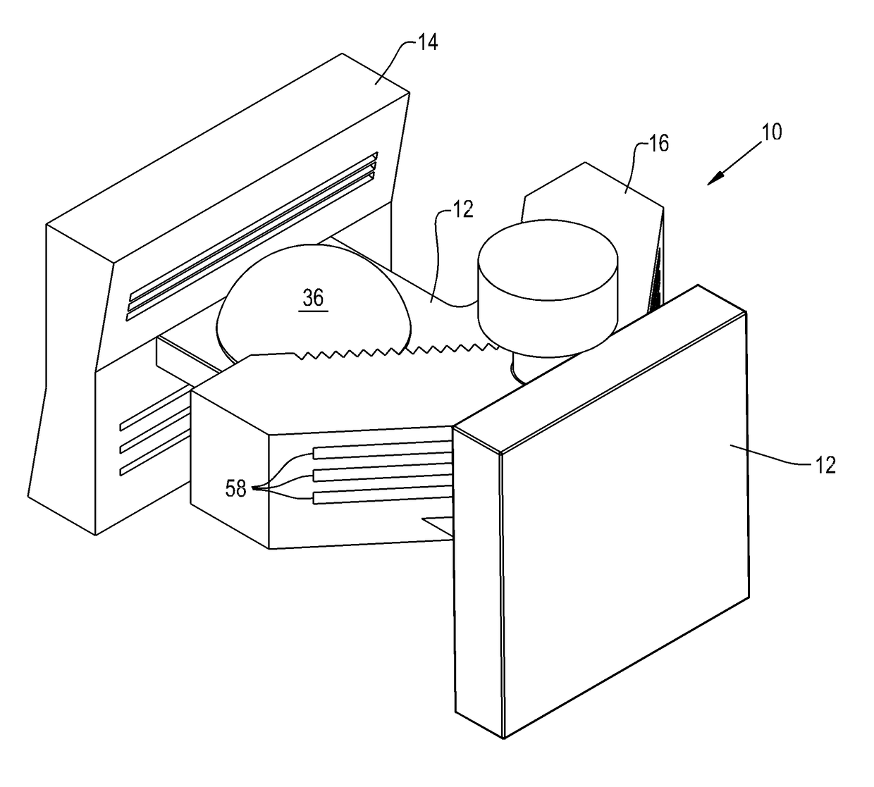
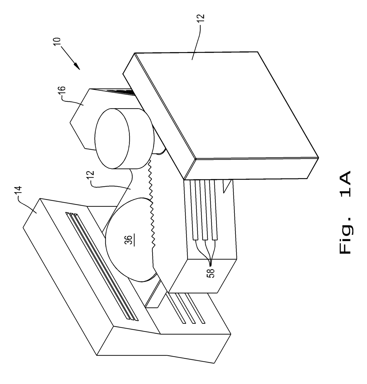
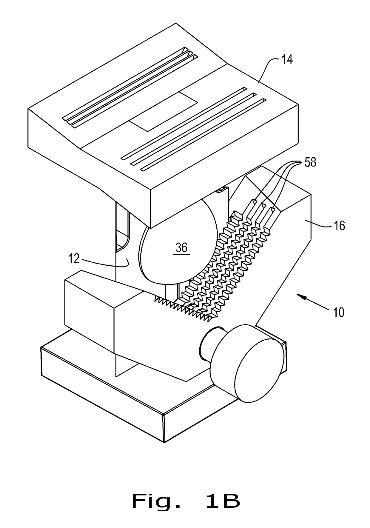
[0035]Referring now to the drawings, and more particularly to FIGS. 1A, 1B, 2 and 3, there is shown an orthopaedic instrument 10 which generally includes a base plate 12, a cutting block 14 and a V-shaped vice member 16.

[0036]Base plate 12 is configured at one end 18 to be coupled with cutting block 14 (FIG. 2). Base plate 12 can be formed as a single, integral unit, or be formed from multiple pieces, removably coupled together for ease of cleaning after use. Base plate 12 includes an elongate planar portion 20 which extends along a longitudinal axis L of base plate 12 and a second portion 21, coupled with and transverse to elongate planar portion 20. Base plate 12 can further include a protrusion 22, for example in the form of a tongue for a tongue and groove joint, extending from end 18 of elongate planar portion 20, as is shown in FIGS. 2 and 3. Base plate 12 includes an elongate member 24 for coupling base plate 12 with vice member 16, for example a tenon 24, such as a dovetail-...


PUM


Abstract

An orthopedic instrument for securing a bone includes a base plate, a cutting block removably coupled with an end of said base plate, and a V-shaped vice member slidingly coupled with the base plate and movable toward and away from the cutting block. The cutting block has a plurality of cutting slots, each of which has a predefined configuration. Further, the vice member is configured for centering the bone and applying a force against the bone toward the cutting block.

Description

CROSS REFERENCE TO RELATED APPLICATIONS[0001]This is a non-provisional application based upon U.S. provisional patent application Ser. No. 61 / 981,245, entitled “ORTHOPAEDIC INSTRUMENT FOR SECURING A BONE”, filed Apr. 18, 2014, which is incorporated herein by reference.BACKGROUND OF THE INVENTION[0002]1. Field of the Invention[0003]The present invention relates to an orthopaedic instrument, and, more particularly, to an orthopaedic instrument for securing and shaping a bone.[0004]2. Description of the Related Art[0005]Orthopaedic patients needing total joint replacement surgery are often found to have severe, pathologic bone loss at the affected joint. In this type of scenario, surgeons often use various types of bone shaping and bone grafting techniques to replace the worn bone. Surgeons are often tasked with having to create a custom-shaped bone manually with only visual guidance. This is not only time consuming, but also very difficult.[0006]What is needed in the art is an orthopa...

Claims


Application Information

Patent Timeline
Patent Type & Authority Patents(United States)
IPC IPC(8): A61F2/46B25B5/14B25B5/10B25B5/16A61B17/15A61B17/88A61F2/30
CPCA61F2/4644A61B17/15B25B5/102B25B5/147B25B5/163A61B17/8866A61F2002/3096A61F2240/002
Inventor KEHRES, CLINTONMUIR, NICHOLASO'REILLY, ANDREWMCDANIEL, JOHN
Owner BIOMET MFG CORP
Why Eureka
Try Eureka