Clothing dryer

a technology for drying racks and dryers, applied in drying machines with non-progressive movements, dryers, textiles and paper, etc., can solve the problems of difficult use of gas as heat source, large maintenance cost of condenser dryers, and difficulty in reducing so as to improve the structure of drainage units and reduce the number of required components

Active Publication Date: 2017-07-11
SAMSUNG ELECTRONICS CO LTD
View PDF15 Cites 14 Cited by
  • Summary
  • Abstract
  • Description
  • Claims
  • Application Information

AI Technical Summary

Benefits of technology

[0011]Therefore, it is an aspect of the present disclosure to provide a clothing dryer that is capable of improving the structure of a drainage unit of the clothing dryer so that the number of required components can be reduced, assembling characteristics of the drainage unit can be improved, and simultaneously condensate water can be prevented from bouncing.
[0026]A protrusion part may be provided at at least a part of the first rib and may protrude from an upper side of the first rib so as to prevent the condensate water flowing into the communication hole from bouncing toward an outer side of the communication hole.
[0029]In accordance with another aspect of the present disclosure, a clothing dryer includes: a body; a drum that is rotatably installed in the body and accommodates an object to be dried; a base that is disposed at a lower portion of the drum; and a drainage unit that is mounted on the base and collects and drains condensate water, wherein the drainage unit includes: a first water tub that collects the condensate water; a plurality of drainage pipes that are combined with the first water tub and cause the condensate water to be drained; and a first water tub cover that protects electronic units positioned at one side of the first water tub and that is combined with the first water tub so that a part of the plurality of drainage pipes is able to be exposed.
[0033]A protrusion part may be provided at at least a part of the first rib and protrude from an upper side of the first rib so as to prevent the condensate water flowing into the communication hole from bouncing toward an outer side of the communication hole.

Problems solved by technology

Since the flow of air constitutes a closed loop, it is difficult to use a gas as a heat source, and condenser dryers use mainly electricity and require a relatively large amount of maintenance cost.
According to the related art, the number of components required for a drainage unit in order for a user to select a drainage method is large, and thus material cost increases.

Method used


Image

  • Clothing dryer
  • Clothing dryer
  • Clothing dryer

Examples


Embodiment Construction

[0057]Reference will now be made in detail to the embodiments of the present disclosure, examples of which are illustrated in the accompanying drawings, wherein like reference numerals refer to like elements throughout.

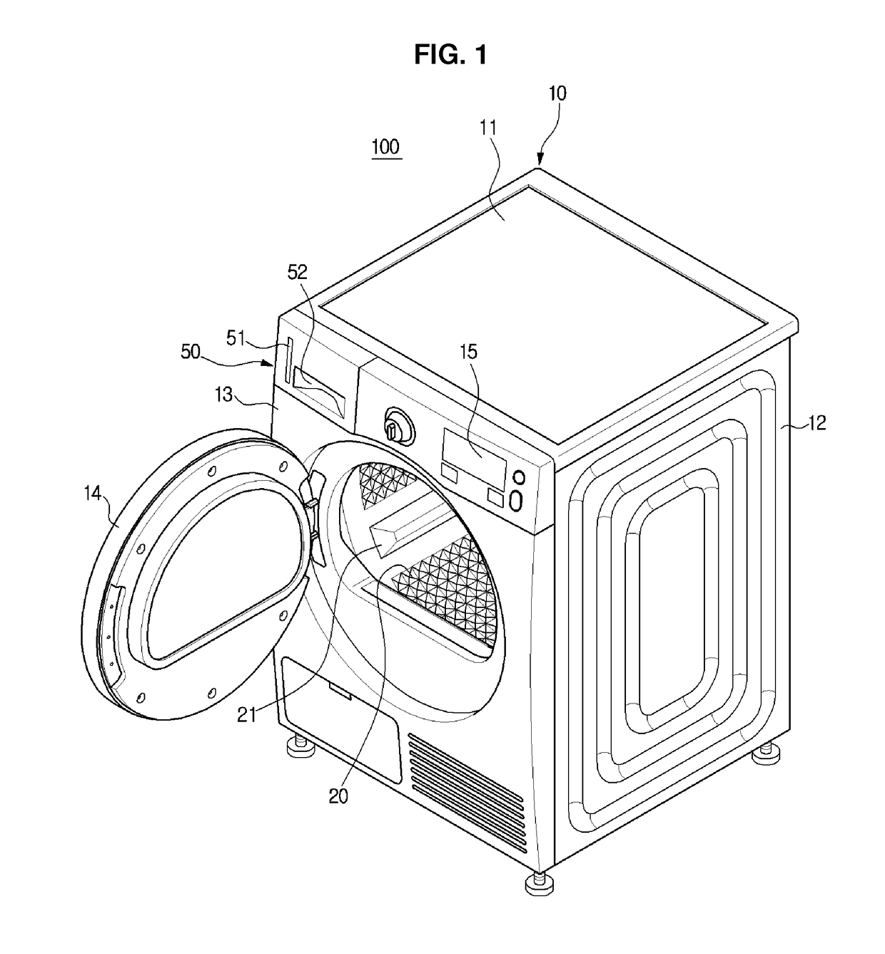
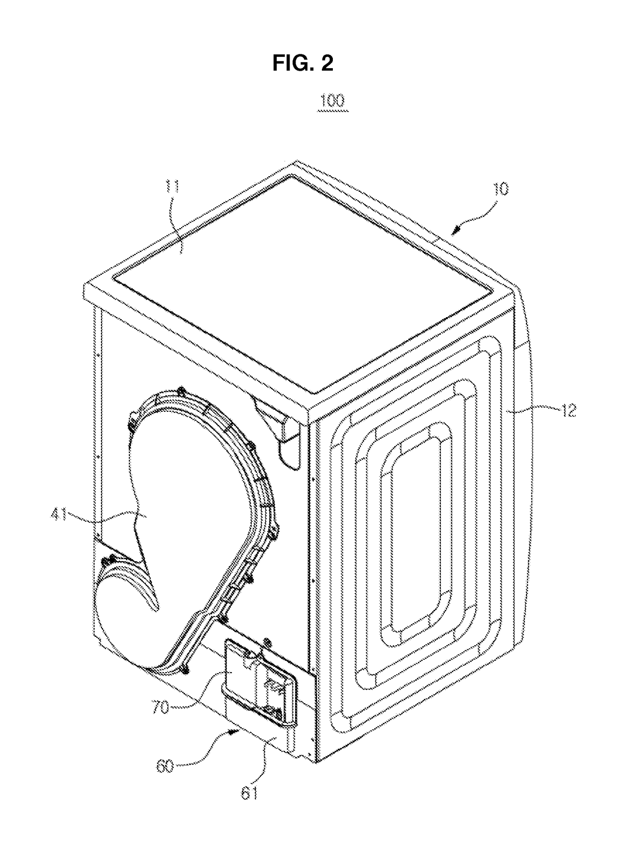
[0058]FIG. 1 is a view illustrating a front side of a clothing dryer according to an embodiment of the present disclosure, FIG. 2 is a view illustrating a rear side of the clothing dryer illustrated in FIG. 1, and FIG. 3 is a view illustrating a configuration of the clothing dryer of FIG. 1.

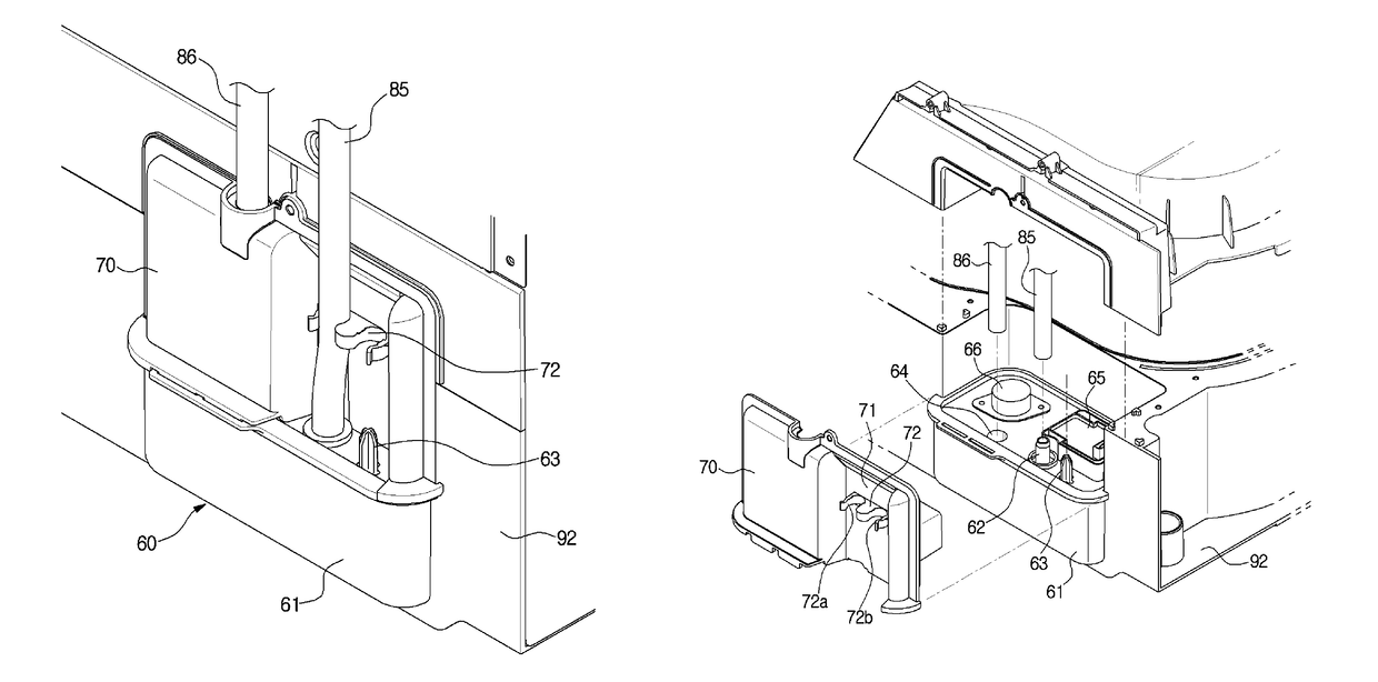
[0059]As illustrated in FIGS. 1 through 3, a clothing dryer 100 includes a body 10, a drum 20, a driving unit 30, a dehumidifying unit (see 80 of FIG. 4), and drainage units 50 and 60.

[0060]The body 10 may include a frame 12, a top cover 11 that covers an upper portion of the frame 12, and a front panel 13 disposed at a front side of the frame 12. The body 10 may further include a first water tub 60 and a second water tub 50 that are the drainage units 50 and 60. The first water tu...


PUM


Abstract

A clothing dryer having an improved structure of a drainage unit thereof, including: a body; a drum; a base that is disposed at a lower portion of the drum; a first water tub that is mounted on the base to collect condensate water generated when a drying operation is performed; and a plurality of drainage pipes that are combined with one side of the first water tub and cause the condensate water to move, wherein, in order to change a position at which the plurality of drainage pipes and the first water tub are combined with each other, the first water tub is combined with edges of the base so that at least a part of the first water tub is able to be exposed to an outside.

Description

CROSS-REFERENCE TO RELATED APPLICATIONS[0001]This application claims the benefit of Korean Patent Application No. P2013-36569, filed on Apr. 3, 2013 in the Korean Intellectual Property Office, the disclosure of which is incorporated herein by reference.BACKGROUND[0002]1. Field[0003]Embodiments of the present disclosure relate to a clothing dryer, and more particularly, to a clothing dryer having an improved structure of a drainage unit thereof.[0004]2. Description of the Related Art[0005]Clothing dryers are devices that dry washed and wet laundry with high-temperature dry air.[0006]In general, clothing dryers are classified into gas dryers and electric dryers depending on a power source or vented dryers and condenser dryers depending on a method of processing moisture absorbed from an object to be dried.[0007]Vented dryers discharge humid air flowing from a drum to the outside through an elongated ventilation duct.[0008]Condenser dryers use a method of removing and drying moisture f...

Claims


Application Information

Patent Timeline
Patent Type & Authority Patents(United States)
IPC IPC(8): F26B11/02D06F58/04D06F58/24
CPCD06F58/04D06F58/24D06F58/20
Inventor LEE, TAE HYUNOAK, SEONG MINKIM, DO HAENGJANG, YONG JOONLEE, JU YOUNG
Owner SAMSUNG ELECTRONICS CO LTD
Why Eureka
Try Eureka