Servo valve

a servo valve and valve body technology, applied in the direction of valves, multiple way valves, mechanical devices, etc., can solve the problems of complex and/or expensive deburring, the inability to provide laterally deflected connection punctures, and the disadvantages of previously known servo valve embodiment, so as to achieve simple and simultaneously operationally safer design, the effect of reducing manufacturing effort and cos

Active Publication Date: 2017-07-11
LIEBHERR AEROSPACE LINDENBERG
View PDF25 Cites 1 Cited by
  • Summary
  • Abstract
  • Description
  • Claims
  • Application Information

AI Technical Summary

Benefits of technology

[0011]It is therefore the object of the present invention to provide an electrohydraulic servo valve of the initially named kind which has a simplified and simultaneously operationally safer design and by which the manufacturing effort and the costs can be substantially reduced.
[0016]The side milling cutter punctures known from the prior art and the distribution bores in the valve block become superfluous due to the formation in accordance with the invention of the control slide valve sleeve with at least one flow passage and preferably with a plurality of flow passages. They can preferably be dispensed with. The volume flow and control flow is only or also transferred via the passages which are applied on the control slide valve sleeve and which are preferably formed in groove-shape. The control slide valve is in this respect suitable to control exactly the volume flow to a consumer, in particular to an actuator. In this respect, the valve block has a good fatigue behavior and endurance behavior. A seal with press-fit plugs can also be omitted in the solution in accordance with the invention.
[0018]The valve block of the electrohydraulic servo valve in accordance with the invention can be made very compact in this manner. The electrohydraulic servo valve in accordance with the invention can therefore produce a great weight advantage over the servo valves known from the prior art. A unit valve block or a valve block of steel and not necessarily of aluminum or titanium can thus be manufactured, which substantially reduces the cost expenditure for the manufacture of such servo valves.
[0022]In this respect, the number of components of the servo valve in accordance with the invention is substantially reduced and the error rate in manufacture is thereby minimized.
[0030]Due to the high precision and corrosion resistance and to the relative small dimensions and, not least, due to the inexpensive manufacture, the electrohydraulic control valve in accordance with the invention is particularly suitable for aviation applications.

Problems solved by technology

However, this embodiment of the previously known servo valves has proved to be disadvantageous.
A further disadvantage of previously known servo valves is that laterally deflected connection punctures have to be provided in the valve block to obtain a transition from the connection bores and crossholes to the control slide valve sleeve.
However, the arising grooves have a critical fatigue behavior and endurance behavior and, apart from this, have to be deburred in a complex and / or expensive manner.
Furthermore, the valve blocks in the previously known servo valves cannot have a compact construction since sufficient materials have to be present for connection bores and crossholes and also for the press-fit plugs.
A further disadvantage of the known servo valves is that, depending on the system pressure and on the weight limit, the valve blocks are produced from aluminum, titanium or steel, which is very cost-intensive in view of the variety of variants.
Additional expenses are also caused by bores for the press-fit plugs, with the plurality of external seals additionally increasing the risk.
The higher number of individual parts of the servo valve results in a lower reliability, on the one hand, and in an increase in the manufacturing costs, on the other hand.

Method used


Image

  • Servo valve
  • Servo valve

Examples


Embodiment Construction

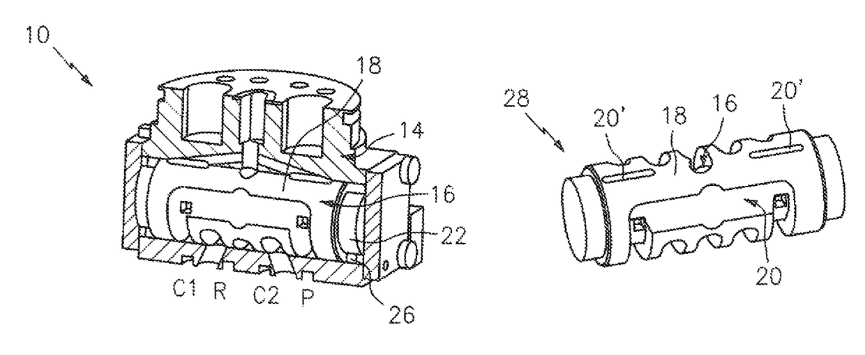
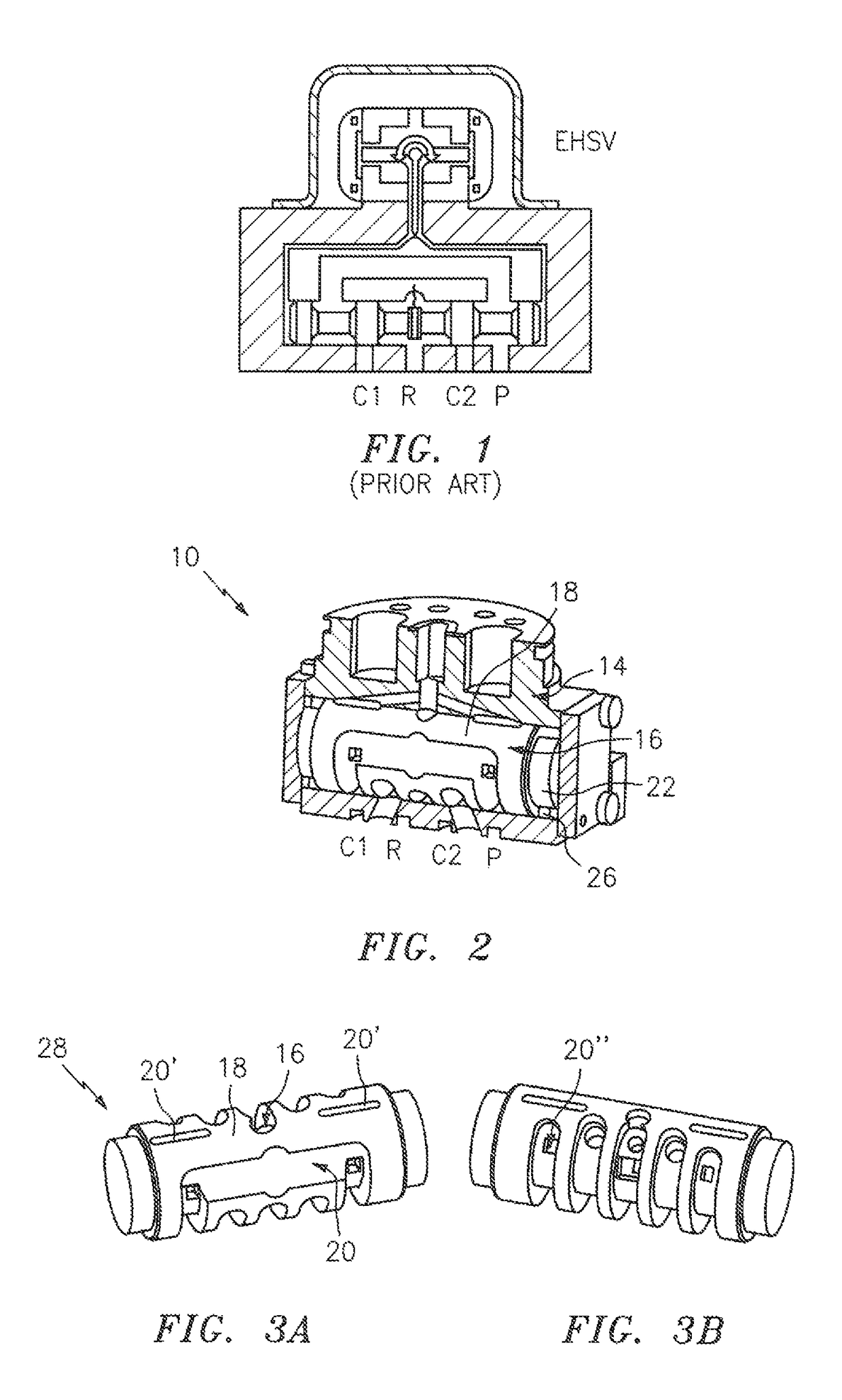
[0038]FIG. 2 shows a sectional representation of an electrohydraulic servo valve 10 in accordance with the invention which is only shown in the region of a second stage which works as a power stage. The pilot stage is not shown here, but is similar to the one shown in FIG. 1. The power stage has a housing which is called a valve block 14 below.

[0039]Furthermore, the power stage has a control slide valve sleeve 16 in which a control slide valve, not shown here, is arranged movable laterally to and fro. The control slide valve is in this respect moved proportionally to the electric input signal of the pilot stage by means of the volume flow by deflection of the pilot stage which is not shown here and which is also called a first stage.

[0040]The control slide valve is moved by the pilot stage in dependence on the electric input signal and allows the volume flow to a consumer such as an actuator to be controlled exactly in dependence on its position.

[0041]The control slide valve sleeve ...


PUM


Abstract

The invention relates to a servo valve, in particular a two-stage or multistage electrohydraulic servo valve, having a first stage which works as a pilot stage, and a second stage which works as a power stage, wherein the second stage has a valve block and a control slide valve sleeve arranged therein and having a jacket surface (18), wherein the jacket surface and / or another region of the control slide valve sleeve is preferably provided with at least one flow passage for transferring control flow and / or volume flow, and wherein a control slide valve is movably arranged in the control slide valve sleeve, wherein at least one of the flow passages is formed by a groove which is arranged in the surface of the control slide valve sleeve and which does not extend sectionally or overall in the peripheral direction of the control slide valve sleeve.

Description

BACKGROUND OF THE INVENTION[0001]The present invention relates to a servo valve, in particular to a two-stage or multistage electrohydraulic servo valve, in accordance with the preamble of claim 1.[0002]Particularly high demands are today made on the operating behavior of the installed hydraulic components within a hydraulic system in hydraulic system engineering. The installed hydraulics should in particular regulate specific hydraulic volume flows or hydraulic volume pressures with high precision in accordance with predefined control signals. Valves suitable for this purpose, in particular continuous valves, allow a continuous transition of the switch positions of the valve to be permitted.[0003]With continuous valves, an electrical input signal for controlling the continuous valve is accordingly converted into a hydraulic output signal. The long-known servo valves belong to a category of continuous valves and allow a highly precise and above all continuous setting of the valve sw...

Claims


Application Information

Patent Timeline
Patent Type & Authority Patents(United States)
IPC IPC(8): F16K11/07F16K31/42F15B13/04F15B13/043
CPCF16K31/42F15B13/0402F15B13/0433F15B13/043
Inventor FRICK, JOERNGAILE, ANTONWEIXLER, FRANZ
Owner LIEBHERR AEROSPACE LINDENBERG
Why Eureka
Try Eureka