Systems and methods for improving energy efficiency of a vehicle based on route prediction

a hybrid vehicle and energy efficiency technology, applied in the direction of battery/fuel cell control arrangement, navigation instruments, instruments, etc., can solve the problems of wasting fuel, wasting energy, and wasting fuel, so as to improve overall energy efficiency and reduce fuel consumption

Active Publication Date: 2017-07-11
TOYOTA JIDOSHA KK
View PDF22 Cites 9 Cited by
  • Summary
  • Abstract
  • Description
  • Claims
  • Application Information

AI Technical Summary

Benefits of technology

[0010]The system / method described above advantageously increases an amount of electrical energy consumption for powering a movement of the wheels when the system / method predicts that the vehicle will travel on the route associated with the charging limitation event. As a result, the vehicle will discharge electrical energy to leave an energy storage margin. An advantage of providing the energy storage margin is that the battery will have sufficient capacity to accept electrical energy generated using regenerative braking. The system / method advantageously allows regenerated energy (that would have otherwise been lost due to the charging limitation event) to be stored in the battery and used to power operations of the vehicle. Yet another advantage of the present invention is that fuel consumption is reduced because the energy that is regenerated and stored in the battery can be effectively used to power operations and / or movements of the vehicle.
[0011]Therefore, the system and method of the present invention provide an effective solution for managing vehicle operations based on route prediction in order to enhance overall energy efficiency and reduce fuel consumption.

Problems solved by technology

However, if the battery is in a full state of charge and does not have the capacity to be charged, the opportunity to store regenerated energy is missed.
If the battery has a full state of charge and without sufficient capacity to be charged, then the opportunity to store regenerated braking energy would be missed.

Method used


Image

  • Systems and methods for improving energy efficiency of a vehicle based on route prediction
  • Systems and methods for improving energy efficiency of a vehicle based on route prediction
  • Systems and methods for improving energy efficiency of a vehicle based on route prediction

Examples


Embodiment Construction

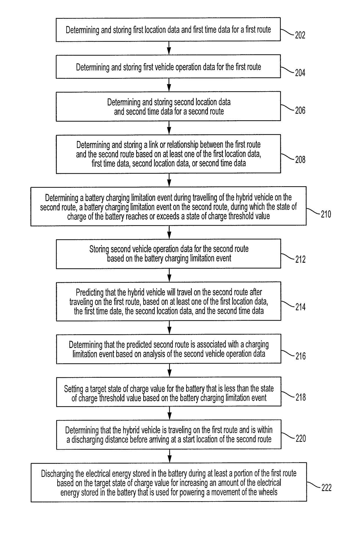
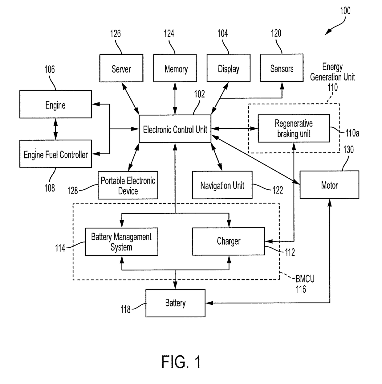
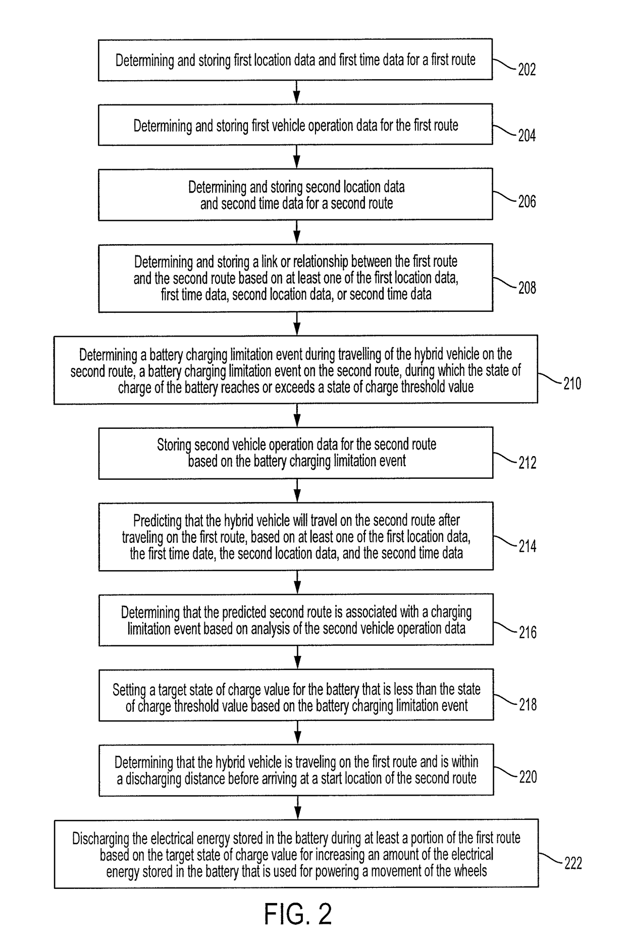
[0021]The present invention relates to improving energy efficiency of a hybrid vehicle. It is desirable to increase the amount of energy that can be recaptured using an energy generation unit. An important source of regeneration of energy is regenerative braking which can generate a considerable amount of electrical energy that can be stored in a battery of the hybrid vehicle. If the battery has a full state of charge and without a capacity to be charged, then the opportunity to store regenerated braking energy would be missed. The present invention is directed to advantageously learning vehicle operation data during previously driven routes, and utilizing the previously learned vehicle operation data for preventing or at least reducing the duration of an energy inefficient event.

[0022]For example, a charging limitation event that occurs during a given identified route can result in an inability of the battery to be charged. The charging limitation event can be stored in the memory ...


PUM


Abstract

A hybrid vehicle includes one or more processors, a memory, an engine, a battery, and a motor. The motor is configured to utilize electrical energy stored in the battery for powering a movement of the wheels or an operation of the hybrid vehicle. A memory stores route data and corresponding vehicle operation data. The one or more processors predict, based on the route data, that the hybrid vehicle will travel on a second route after travelling on a first route. The one or more processors predict, based on the vehicle operation data, that the state of charge (SOC) of the battery will reach or exceed a threshold value during the second route. The one or more processors set a target SOC for the battery. The one or more processors discharge the electrical energy stored in the battery during the first route based on the target SOC value.

Description

BACKGROUND[0001]Field[0002]The present invention relates to systems and methods for improving energy efficiency of a hybrid vehicle and for route prediction.[0003]Description of the Related Art[0004]With global energy prices rapidly increasing, users of vehicles that utilize various forms of energy are increasingly interested in enhancing the overall energy efficiency of the vehicle. The overall energy efficiency accounts for consumption of various forms of energy including fuel energy and electrical energy.[0005]It is desirable to enhance the ability of hybrid vehicles to regenerate energy for storage in a battery (when regeneration is available). For example, when a hybrid vehicle travels downhill for a relatively long distance, regenerative braking can contribute significantly to battery charging. However, if the battery is in a full state of charge and does not have the capacity to be charged, the opportunity to store regenerated energy is missed. Therefore, it is desirable to p...

Claims


Application Information

Patent Timeline
Patent Type & Authority Patents(United States)
IPC IPC(8): B60L11/18B60L3/00G01C21/34B60L7/10B60L3/04B60L15/20B60L3/12B60L7/14B60L11/14B60L50/16
CPCG01C21/3469B60L3/0046B60L3/04B60L3/12B60L7/14B60L11/14B60L11/1816B60L11/1861B60L15/2009B60L15/2045B60L2210/10B60L2210/40B60L2240/12B60L2240/421B60L2240/423B60L2240/441B60L2240/443B60L2240/545B60L2240/547B60L2240/549B60L2240/622B60L2240/642B60L2240/645B60L2250/16B60L2260/52B60L2260/54Y02T10/7005Y02T90/127Y02T90/14Y02T90/16Y02T90/162B60L50/16B60L53/14B60L58/13B60L58/24Y02T10/64Y02T10/70Y02T10/7072Y02T10/72Y02T90/12
Inventor PAYNE, JOSHUA D.DUFFORD, MOHAMMAD E.
Owner TOYOTA JIDOSHA KK
Why Eureka
Try Eureka