
Method and apparatus for rasterizing and encoding vector graphics

Active Publication Date: 2017-07-11
TERADICI CORP
View PDF11 Cites 52 Cited by
  • Summary
  • Abstract
  • Description
  • Claims
  • Application Information

AI Technical Summary

Benefits of technology

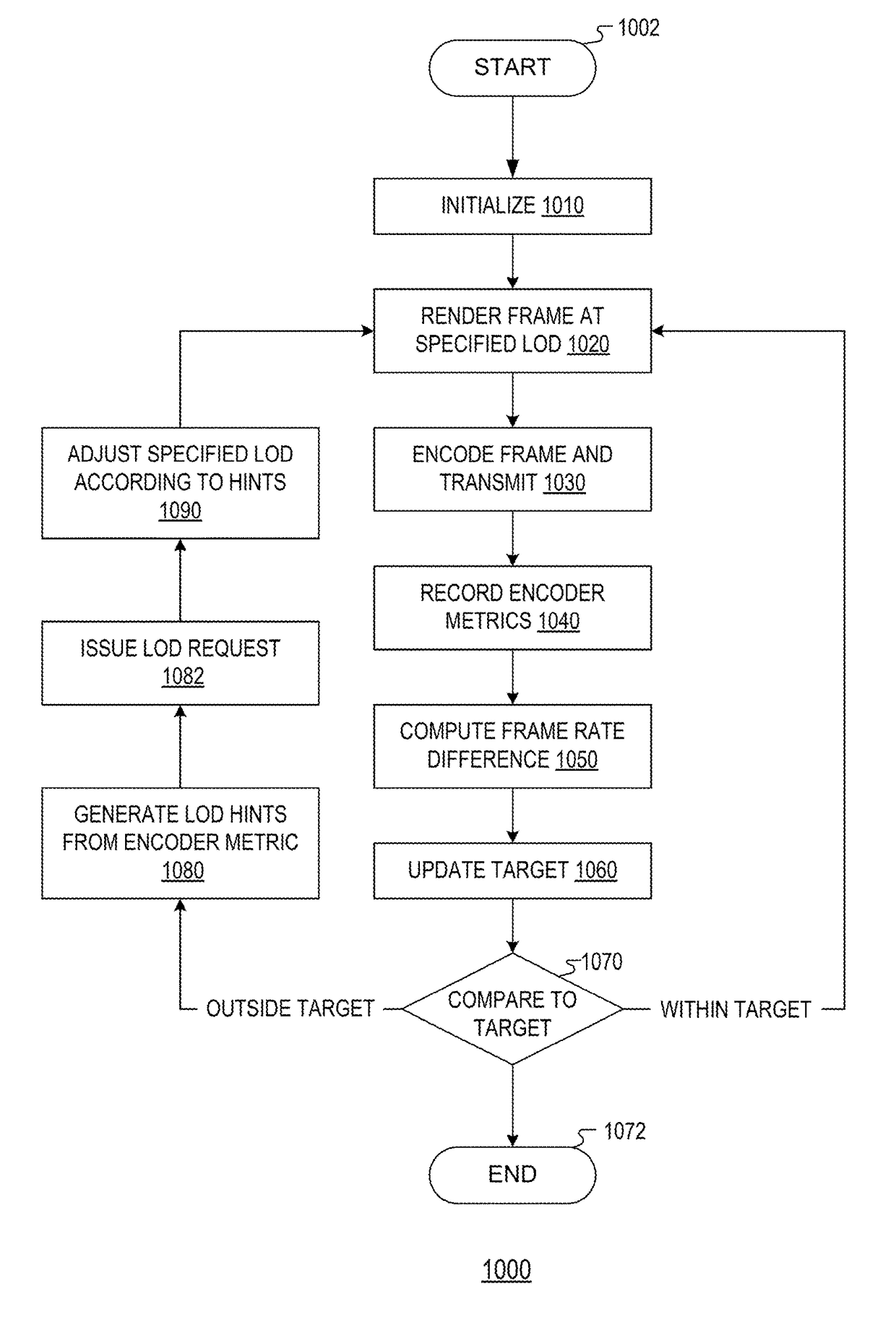
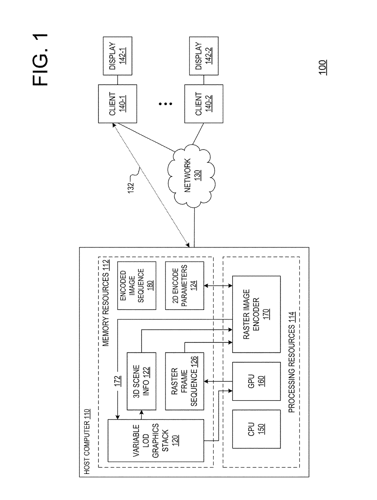
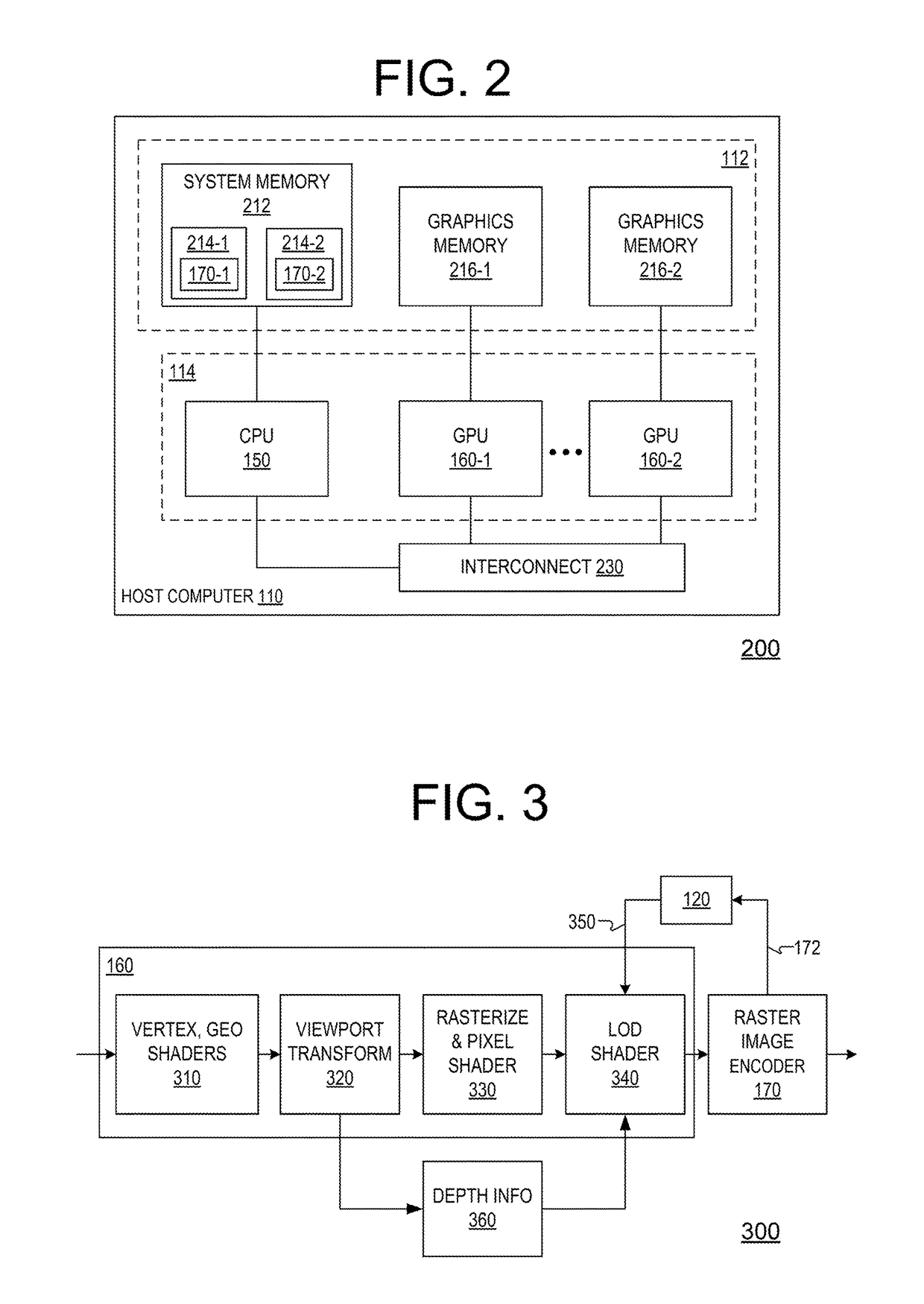
The present invention relates to a method and apparatus for rasterizing and encoding vector graphics. The technical effect of the invention is that it allows for the adjustment of image detail based on the difference between the transmission frame rate of the image encoder and the raster sequence frame rate of the raster sequence of images rasterized by the graphics processing unit (GPU). This results in a smoother and more detail-oriented output image.

Problems solved by technology

One challenge with such a configuration is that many LAN and WAN networks have insufficient capacity to communicate the image frame sequence at the original rendered frame rate and acceptable quality.
Unless the GPU is throttled to render at the same frame rate of the encoded image frame sequence, this becomes highly inefficient for both central processing unit (CPU) and GPU resources, a problem exacerbated by virtualization of GPU and CPU resources in which power utilization is paramount.
While modern raster image encoders themselves are enabled to regulate image quality and frame rate based on the spatial frequency characteristics of content or characteristics of image motion, they too do not distinguish content importance beyond cursor location or position on a 2D display.
The problem of efficiency is further exacerbated by computer-aided design (CAD) application software which in some cases, indiscriminately reduces the level of detail (LOD) of a 3D scene under motion to sustain a high rendering rate but resultant shaded surface artifacts are inefficient to encode and negatively impact throughput.
Such systems require client GPU resources for rendering and composition which detracts from the benefits of centralizing graphics processing in the datacenter.

Method used


Image

  • Method and apparatus for rasterizing and encoding vector graphics
  • Method and apparatus for rasterizing and encoding vector graphics
  • Method and apparatus for rasterizing and encoding vector graphics

Examples


Embodiment Construction

[0034]The invention may be implemented in numerous ways, including as a process, an article of manufacture, an apparatus, a system, and as a set of computer-readable descriptions and / or instructions embedded on and / or in a computer-readable medium such as a computer-readable storage medium. In this specification, these implementations, or any other form that the invention may take, may be referred to as techniques. The Detailed Description provides an exposition of one or more embodiments of the invention that enable improvements in features such as performance, power utilization, cost, scalability, efficiency, and utility of use in the field identified above. The Detailed Description includes an Introduction to facilitate the more rapid understanding of the remainder of the Detailed Description. The invention encompasses all possible modifications and variations within the scope of the issued claims.

[0035]The term processor as used herein refers to any type of processor, central pr...


PUM


Abstract

The present invention describes exemplary embodiments of a method and apparatus for rasterizing and encoding vector graphics. The method comprises determining, by an image encoder, a difference between a transmission frame rate of an image encoder and a raster sequence frame rate of a raster sequence of images rasterized by a graphics processing unit (GPU); and adjusting, by the GPU, image detail of the raster sequence according to the difference.

Description

BACKGROUND OF THE INVENTION[0001]Field of the Invention[0002]Embodiments of the present invention relate generally to a method and apparatus for rasterizing and encoding vector graphics.[0003]Description of the Related Art[0004]Traditionally, graphics processing units (GPUs) have been deployed in personal computers (PCs) or workstations with direct coupling to local display resources to render image sequences at high frame rates. More recently however, GPUs have been deployed as centralized resources in corporate data centers and cloud infrastructure separated from client terminals by local area network (LAN) or wide area network (WAN) topologies. An image frame sequences rendered by the GPU is encoded, communicated over the network to the client terminal where it is decoded and displayed. One challenge with such a configuration is that many LAN and WAN networks have insufficient capacity to communicate the image frame sequence at the original rendered frame rate and acceptable qual...

Claims


Application Information

Patent Timeline
IPC IPC(8): G06T9/00G06T15/60G06T15/04G06T15/06G06T15/00G06T7/00G06T15/80
CPCG06T9/00G06T15/80G06T15/60G06T15/04G06T15/06G06T15/005G06T7/0081G06T7/0085G06T7/11G06T7/13G06F30/00
Inventor MAIN, IAN CAMERONHOBBS, DAVID VICTORLONGHURST, PETER WILLIAM
Owner TERADICI CORP
Learn More