Adaptive optical image reader

an optical image reader and adaptive technology, applied in the field of optical image reader apparatus and methods, can solve the problems of inconvenient data acquisition, inconvenient data acquisition, and high cost, and achieve the effect of improving data acquisition accuracy and data acquisition tim

Inactive Publication Date: 2005-03-17
HAND HELD PRODS
View PDF74 Cites 145 Cited by
  • Summary
  • Abstract
  • Description
  • Claims
  • Application Information

AI Technical Summary

Benefits of technology

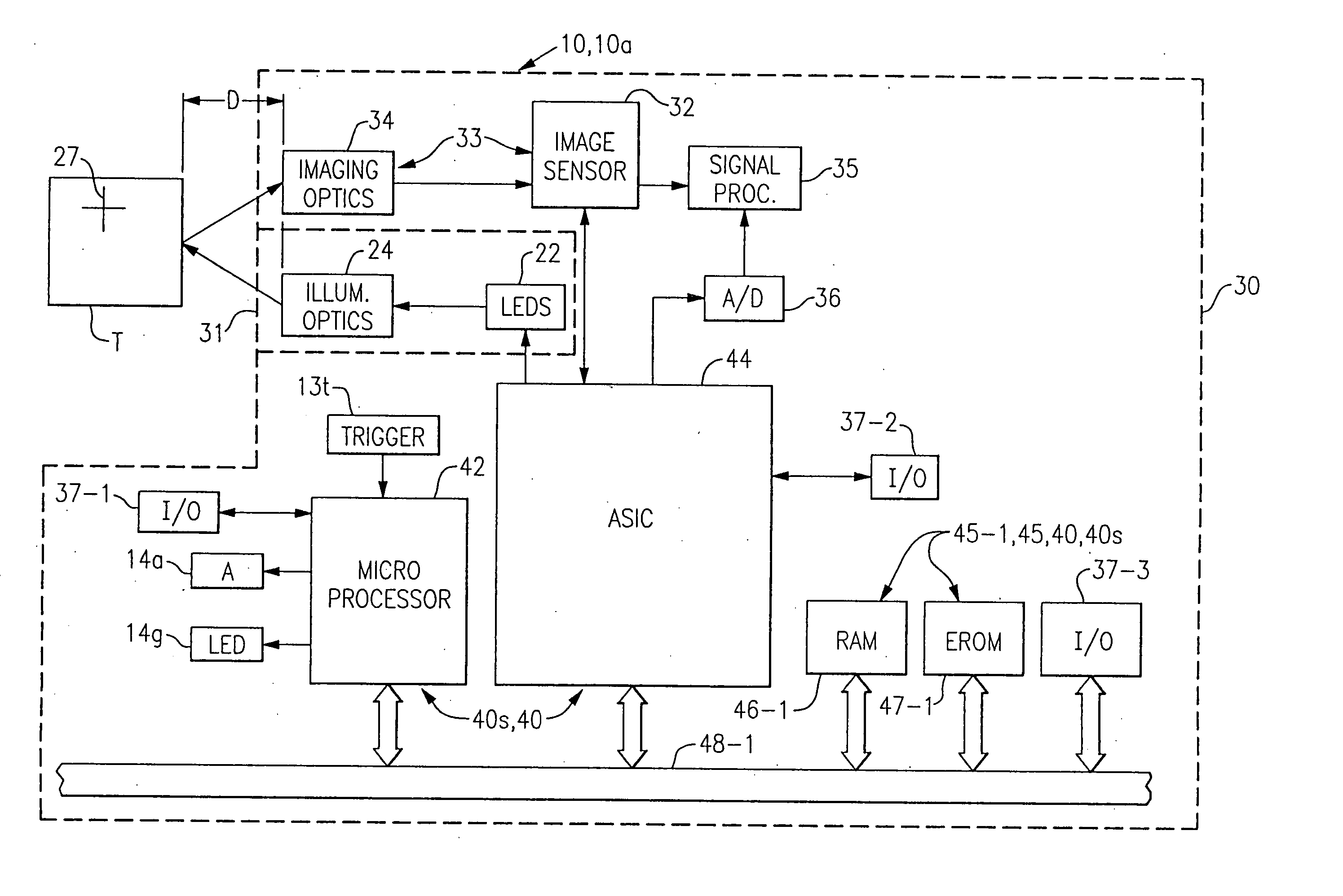
[0012] In accordance with embodiments of the invention described and claimed herein, there are provided an optical image reading system (including scanning and decoding components) and method suitable for use with bar code readers, bar code scanning engines, portable data terminals (PDTs) and other device form factors as those skilled in the art will appreciate, that are adaptable to the object environment and / or input conditions, and by which result improved data acquisition time and data acquisition accuracy. In an aspect, the reader will automatically adapt to different read conditions or environments.

Problems solved by technology

A digitization method that may be useful for digitizing image data under a first imaging condition or which corresponds to a first type of symbol may not be useful for digitizing image data captured under a second set of imaging conditions or which corresponds to a second type of symbol, for example.
It can be appreciated, therefore, that the above approach can be extremely time consuming and prone to repetitive failure.
If a bar code read is attempted outside of the designed read range, neither the system components nor the reader algorithms will be sufficient to provide a successful first read attempt, leading to business inefficiencies in the long run.

Method used


Image

  • Adaptive optical image reader
  • Adaptive optical image reader
  • Adaptive optical image reader

Examples


example 1

Voting

[0111] In linear bar code decoding, the process of verifying a bar code read by successively decoding the same bar code in multiple scans is used to eliminate cases where the bar code is not interpreted correctly or where a noisy signal may randomly generate a bar code read. This will be henceforth referred to as voting the bar code. To find the correct digitization method for the bar code itself, the system cycles through the different digitizers running on the system. However, once a digitizer has yielded what appears to be valid bar code data, then the system will “lock on” to that digitizer, and use it exclusively for the next few scans in an attempt to vote the bar code and get a successful read. For instance, if a certain digitizer Dx found what is believed to be bar code data, the control circuit 140 would then configure the system to use that same digitizer Dx and only that digitizer for the next N number of scans (where usually N>1) to ensure that a significant numbe...

example 2

Stacked Linear

[0113] Another instance where the control circuit 140 can configure the system such that a given digitizer is used for the next subsequent N scans is with the case of a stacked linear bar code such as PDF417. Stacked linear bar codes inherently require multiple single line scans in order to successfully decode. For example, where the system is cycling through the plurality of digitizers and sees a valid decode of a row of stacked linear data, the system is configured to use that same digitizer exclusively for the next N scans (again usually N>1). If a subsequent line of data from that stacked linear code is decoded during those N times of using the same digitizer, the system is then refreshed to use that digitizer for another N scans. However, if or when enough data is received to create a successful decode, or if the number of times to use a given digitizer N counts down to zero having not seen another row of stacked linear data, the system is then reset to cycle thr...

example 3

Statistical Decision Making

[0115] In a contemplated aspect, the multiple digitizers would be used to essentially optimize scanning in a given environment. For example, statistical records would kept internal to the system during the process of cycling through the digitizers to rank all of the digitizers in the order of their success rate at finding bar code data (i.e. not counting the times when a specific digitizer is used repeatedly for voting). Then, an intelligent decision could be made as to the order of how the digitizers would be run through. For instance, the first digitizer in this ranking would be the one that was statistically most successful at finding a bar code, the second would be the second most successful, and so on. It may be that one digitizer happens to be twice as successful as the combined success rate of each of the others, in which case that one digitizer would get called not only with the first scan, but also with the third, and fifth, etc. Assuming that th...


PUM


Abstract

A digital image reading system including an image sensor and a computer that is programmed to adjust the frame rate of the image sensor, and to obtain a maximum frame rate of the image sensor for obtaining an acceptable image. An algorithm for adjusting the frame rate evaluates image parameters and calculates new exposure times, gain values, and exposure settings to support a maximum frame rate of the image sensor. A process for obtaining an acceptable image with an image reader evaluates an image signal level and adjusts the frame rate if the signal level is outside of a predetermined range. The process adjusts the image sensor to run at a maximum operational frame rate. A digital image reading system including multiple separate digitizers for use in various read environments and under various read conditions.

Description

CROSS REFERENCE TO RELATED APPLICATIONS [0001] This application is a continuation-in-part of U.S. patent application Ser. No. 09 / 904,697 filed Jul. 13, 2001. This application also claims the priority of U.S. Provisional Application No. 60 / 470,016 filed May 12, 2003. The priorities of the above applications are claimed and the above applications are incorporated herein by reference.FIELD OF THE INVENTION [0002] Embodiments of the invention are directed to optical image reader apparatus and methods and, more particularly, to an optical image reader apparatus and method providing improved functionality and adaptability to object environments. BACKGROUND OF THE INVENTION [0003] Optical readers tend to fall into one of three classes: wand readers, laser scan engine optical readers and image sensor based optical readers. [0004] Wand readers generally comprise a single light source and single photodetector housed in a pen shaped housing. A user drags the wand reader across a decodable symb...

Claims


Application Information

Patent Timeline
Patent Type & Authority Applications(United States)
IPC IPC(8): G06K7/10G06K7/14G06K9/24
CPCG06K7/10722G06K7/10851G06K7/10752
Inventor MEIER, TIMOTHYLONGACRE, ANDREW JR.HAWLEY, THOMASPETTINELLI, JOHNHUSSEY, ROBERT M.
Owner HAND HELD PRODS
Why Eureka
Try Eureka