
Key input device for multifunction peripheral equipment

Active Publication Date: 2017-07-11
BROTHER KOGYO KK
View PDF15 Cites 3 Cited by
  • Summary
  • Abstract
  • Description
  • Claims
  • Application Information

AI Technical Summary

Benefits of technology

This patent is about a key input device and a method of manufacturing it. The invention aims to improve the design of key input devices by eliminating limitations caused by external factors such as the strength of the surface where the device is used and increasing its resistance to damage caused by static electricity. The technical effects of this invention are to improve the overall performance and reliability of key input devices, making them easier to install and more durable.

Problems solved by technology

In such a user interface, a layout of the keys is limited in some cases by the workability of the surface member.
Thus, even in the case where the keys are preferably arranged at a considerably short distance (e.g., a distance less than or equal to 0.51 mm) from the viewpoint of design, it may be difficult to provide a desired design because the distance between the key holes cannot be made extremely short.

Method used


Image

  • Key input device for multifunction peripheral equipment
  • Key input device for multifunction peripheral equipment
  • Key input device for multifunction peripheral equipment

Examples


Embodiment Construction

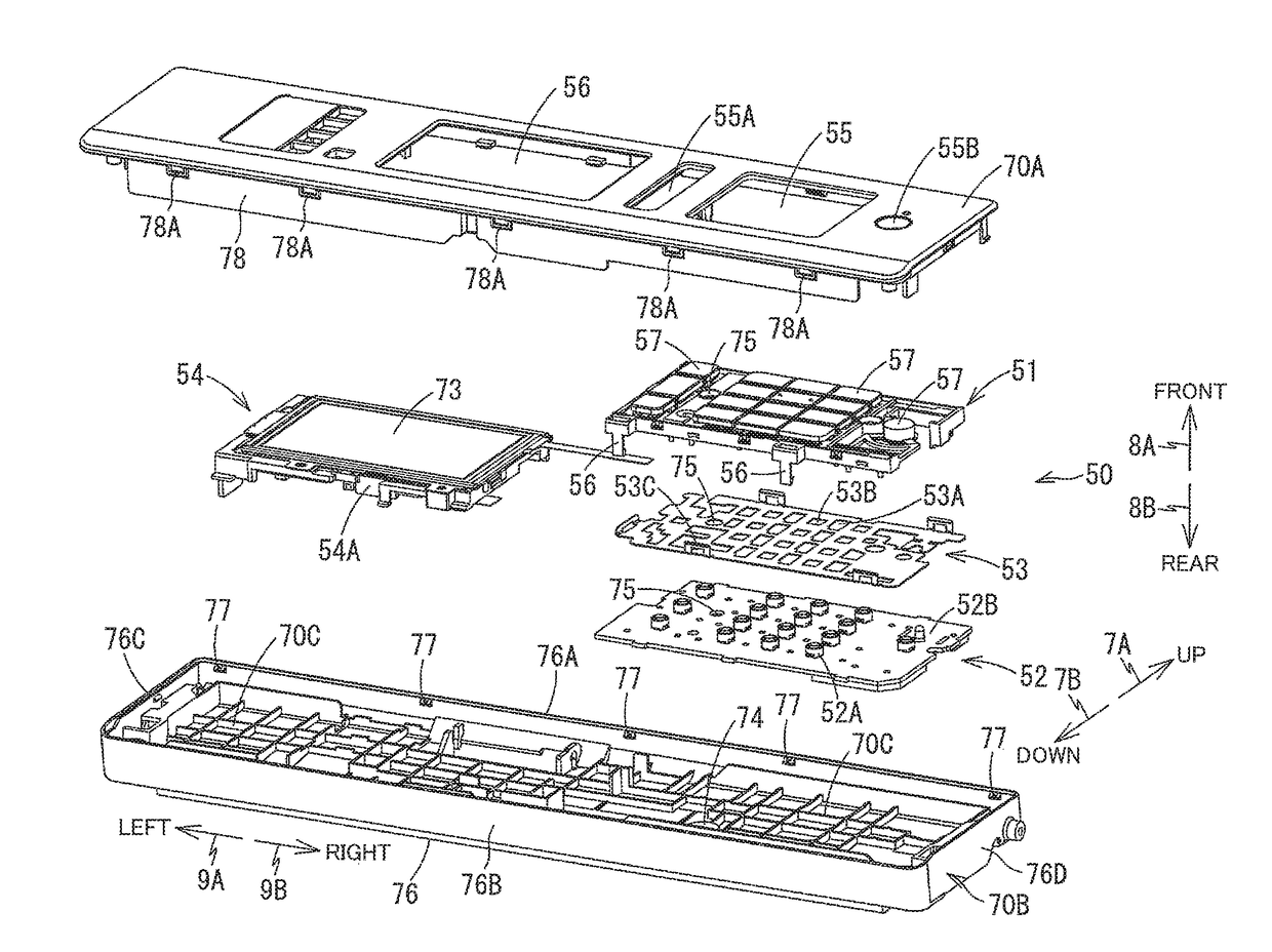
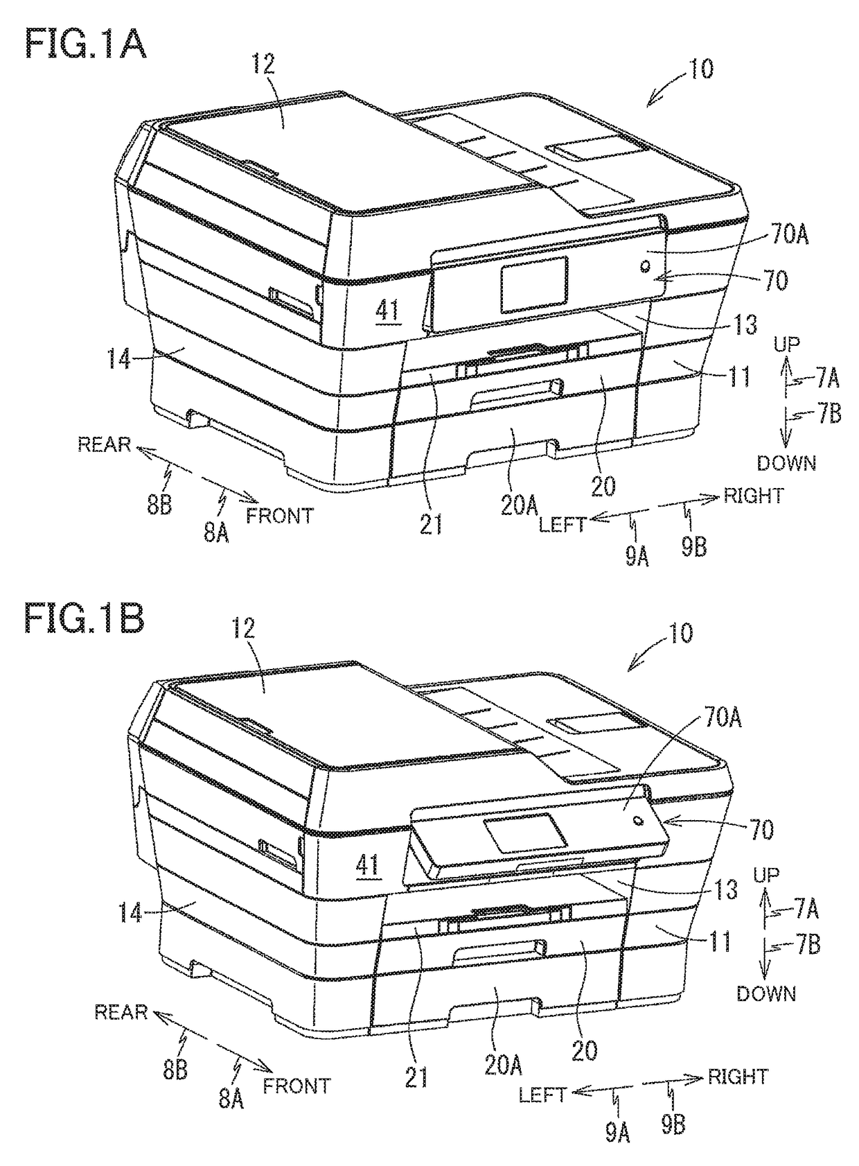
[0020]Hereinafter, there will be described one embodiment by reference to the drawings. It is to be understood that the following embodiment is described only by way of example, and the disclosure may be otherwise embodied with various modifications without departing from the scope and spirit of the disclosure. A multi-function peripheral (MFP) 10 is used in a state illustrated in FIG. 1. In the following explanation, up and down directions 7A, 7B are defined in this state. Also, front and rear directions 8A, 8B are defined by regarding a side of the MFP 10 on which an opening 13 is formed as a front side (a front surface 41), and left and right directions 9A, 9B are defined in a state in which the MFP 10 is viewed from the front. Also, for the explanation of components, the up and down directions 7A, 7B, the front and rear directions 8A, 8B, and the left and right directions 9A, 9B are defined based on a state in which the components are assembled to the MFP 10. For a panel 70 as a...


PUM


Abstract

A key input device includes: keys each including a contact portion provided on its back surface; a holder holding the keys movably; a conductive member opposed to the holder; and a circuit board having a switch surface and switches arranged on the switch surface and each contactable with the contact portion of a corresponding key. The conductive member is interposed between the switch surface and the holder. The holder has first through holes, and the conductive member has second through holes. At least one of the contact portion and the switch is inserted in a corresponding one of the first through holes, and at least one of the contact portion and the switch is inserted in a corresponding one of the second through holes.

Description

CROSS REFERENCE TO RELATED APPLICATION[0001]The present application claims priority from Japanese Patent Application No. 2015-074343, which was filed on Mar. 31, 2015, the disclosure of which is herein incorporated by reference in its entirety.BACKGROUND[0002]Technical Field[0003]The following disclosure relates to a key input device that is an assembly including a plurality of keys and capable of outputting a signal corresponding to a pressed one of the keys, to a method of manufacturing the key input device, and to an image recording apparatus.[0004]Description of the Related Art[0005]Various devices include a key input device as a user interface. Image recording apparatuses such as ink-jet recording apparatuses and copying machines generally include a user interface provided on a front and upper portion of a body of the apparatus, and the user interface includes a key input device having a plurality of keys, for example. A surface member of such a user interface has a plurality o...

Claims


Application Information

Patent Timeline
IPC IPC(8): H01H9/26G06F3/02H01H13/702H01H13/88H04N1/00H01H13/7057
CPCH01H13/702G06F3/02H01H13/7057H01H13/88H04N1/00384H01H2221/044H01H2221/05H01H2233/034H01H2233/054H01H2233/056H01H2239/004H04N1/00411H04N2201/0094G06F3/0202
Inventor NAMBA, MAMORU
Owner BROTHER KOGYO KK
Learn More