Drive mechanism for drug delivery pumps with integrated status indication

a technology of driving mechanism and drug delivery pump, which is applied in the direction of intravenous device, other medical devices, infusion syringes, etc., can solve the problems of limiting the flow rate and profile of simple therapy, affecting the patient's mobility and lifestyle, and limiting the control of drug administration through transdermal patch, so as to achieve accurate confirmation of drug dose delivery

Active Publication Date: 2017-07-18
UN HOLDINGS LLC
View PDF156 Cites 32 Cited by
  • Summary
  • Abstract
  • Description
  • Claims
  • Application Information

AI Technical Summary

Benefits of technology

[0008]The present invention provides drive mechanisms with integrated status indication, drug delivery pumps which incorporate such drive mechanisms, the methods of operating such devices, and the methods of assembling such devices. The drive mechanisms of the present invention provide integrated status indication features which provide feedback to the user before, during, and after drug delivery. For example, the user may be provided an initial feedback to identify that the system is operational and ready for drug delivery. Upon activation, the system may then provide one or more drug delivery status indications to the user. At completion of drug delivery, the drive mechanism and drug pump may provide an end-of-dose indicati...

Problems solved by technology

Bolus injections often imperfectly match the clinical needs of the patient, and usually require larger individual doses than are desired at the specific time they are given.
Continuous delivery of medicine through gravity-feed systems compromises the patient's mobility and lifestyle, and limits the therapy to simplistic flow rates and profiles.
Transdermal patches often require specific molecular drug structures for efficacy, and the control of the drug administration through a transdermal patch is sev...

Method used


Image

  • Drive mechanism for drug delivery pumps with integrated status indication
  • Drive mechanism for drug delivery pumps with integrated status indication
  • Drive mechanism for drug delivery pumps with integrated status indication

Examples


Embodiment Construction

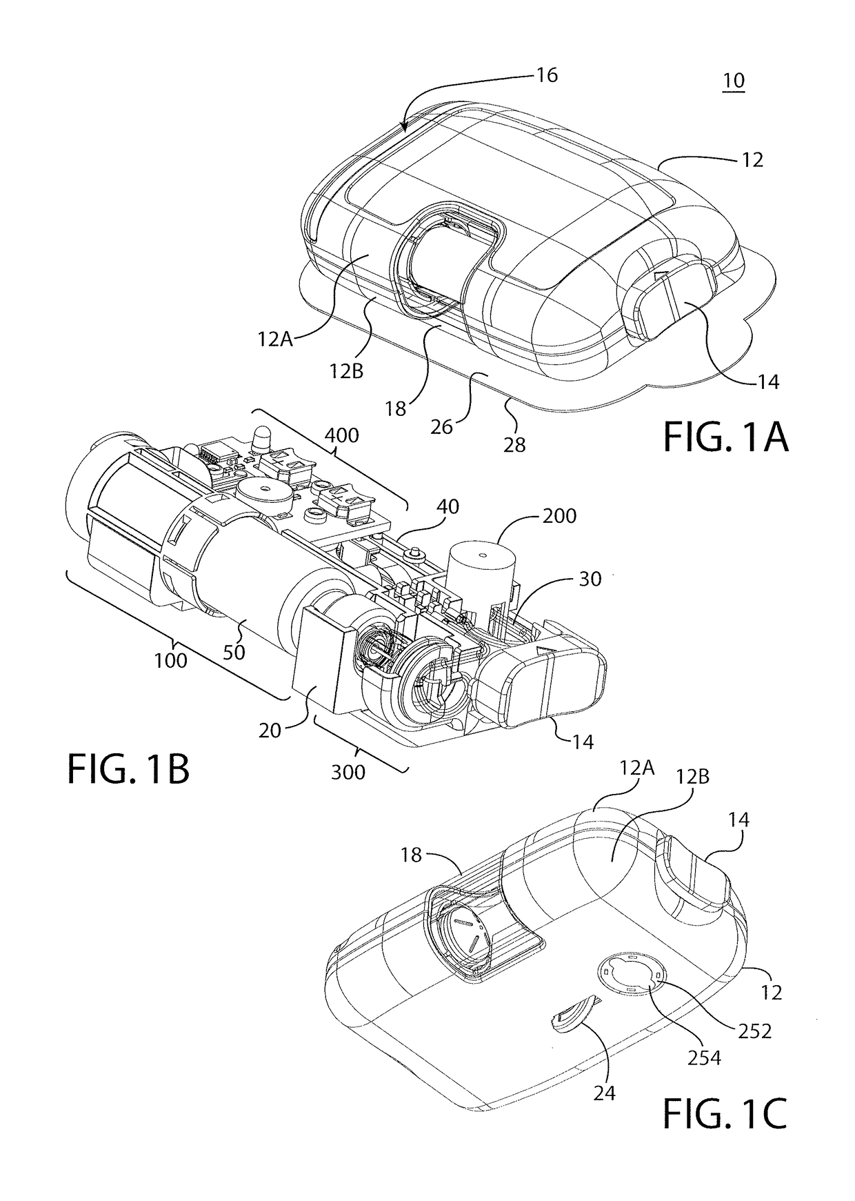
[0056]As used herein to describe the drive mechanisms, drug delivery pumps, or any of the relative positions of the components of the present invention, the terms “axial” or “axially” refer generally to a longitudinal axis “A” around which the drive mechanisms are preferably positioned, although not necessarily symmetrically there-around. The term “radial” refers generally to a direction normal to axis A. The terms “proximal,”“rear,”“rearward,”“back,” or “backward” refer generally to an axial direction in the direction “P”. The terms “distal,”“front,”“frontward,”“depressed,” or “forward” refer generally to an axial direction in the direction “D”. As used herein, the term “glass” should be understood to include other similarly non-reactive materials suitable for use in a pharmaceutical grade application that would normally require glass, including but not limited to certain non-reactive polymers such as cyclic olefin copolymers (COC) and cyclic olefin polymers (COP). The term “plasti...


PUM


Abstract

A drive mechanism includes a housing, a piston adapted to impart movement to a plunger seal within a drug container, a plurality of biasing members disposed in parallel, and a retainer. The biasing members are disposed to release energy to cause movement of the piston from a retracted first position to the extended second position, the piston bearing against the plunger seal to dispense medicine. The retainer is disposed to maintain the biasing members in the energized position and to release the biasing members to permit the piston to dispense the medicine. The drive mechanism may also include an end-of-dose indicator to identify at least one of when the sleeve assembly is disposed subjacent a window in the housing, the relative motion of the sleeve assembly with reference to the window or another reference component, the stoppage of such motion, and the rated or change of rate of motion.

Description

CROSS-REFERENCE TO RELATED APPLICATIONS[0001]This application is a continuation-in-part of P.C.T. Application PCT / US2014 / 013005 and U.S. application Ser. No. 14 / 163,690, both filed Jan. 24, 2014, and which both claim priority to U.S. Provisional Application 61 / 756,667, filed on Jan. 25, 2013, and U.S. Provisional Application 61 / 912,642, filed Dec. 6, 2013. U.S. application Ser. No. 14 / 163,690 is also a continuation-in-part of U.S. application Ser. No. 13 / 600,114 filed Aug. 30, 2012, which claims priority to U.S. Provisional Application 61 / 530,788 filed Sep. 2, 2011. This application claims priority to each of these applications, each of which is incorporated by reference herein in its entirety for all purposes.FIELD[0002]THIS INVENTION relates to drug delivery pumps. More particularly, this invention relates to drive mechanisms with integrated status indication, drug delivery pumps with status integrated drive mechanisms, the methods of operating such devices, and the methods of ass...

Claims


Application Information

Patent Timeline
IPC IPC(8): A61M5/145A61M5/142A61M5/24
CPCA61M5/14216A61M5/14248A61M5/14566A61M2005/14252A61M2005/2474A61M2205/58A61M2205/82A61M5/1454A61M5/172A61M2205/3317A61M2205/3379A61M2205/50
Inventor AGARD, RYAN M.HANSON, IAN B.CICCARELLI, NICHOLAS J.O'CONNOR, SEAN M.BOKELMAN, KEVINBENTE, IV, PAUL F.LOVE, JOHN C.HATCH, CHRISTOPHER EDWARD
Owner UN HOLDINGS LLC
Why Eureka
Try Eureka