Hadron radiation installation and verification method

a radiation installation and verification method technology, applied in radiation therapy, therapy, instruments, etc., can solve the problems of large neutron emission, prompt gamma rays, and severely restricted real-time proton beam penetration depth measurement potential, and achieve the effect of greater detector accuracy

Inactive Publication Date: 2017-07-18
TECH UNIV DELFT
View PDF13 Cites 2 Cited by
  • Summary
  • Abstract
  • Description
  • Claims
  • Application Information

AI Technical Summary

Benefits of technology

[0018]By allowing for variation of the slit width the utility of the installation is significantly increased, notably when in a suitable design the slit width can be varied in the course of a radiation session, e.g. to optimize the functioning of the radiation beam range sensor device and / or to enhance or optimize one or more of the resolution, accuracy, quality, and reliability of the gamma camera.
[0098]In this design the first and second slit passages, and possibly one or more central slit passages when present, effectively allow to mimic an ordinary singular slit passage type slit aperture. The advantage of the inventive slit aperture design lies mainly in the ability to counteract the problem of penetration of gamma radiation through portions, mainly edge portions, of the collimator along the boundaries of the slit aperture or slit passages. Effectively an ordinary slit aperture having a particular opening angle can be replaced by the inventive design with the advantage that now the collimator portions bounding the longitudinal sides of each slit passage can be made less penetrable for gamma radiation, with resulting enhancement of the quality and / or efficiency of the imaging of the penetration of the pencil beam into the target. The fifth aspect of the invention also may be done with thick collimator walls, e.g. having a thickness greater than 30 millimeters, e.g. greater than 40 or even greater than 80 millimeters.

Problems solved by technology

Nuclear fragmentation reactions occur along the track in the target resulting in the emission of large numbers of neutrons and prompt gamma rays.
The potential for real-time measurement of proton beam penetration depth is therefore severely restricted.

Method used


Image

  • Hadron radiation installation and verification method
  • Hadron radiation installation and verification method
  • Hadron radiation installation and verification method

Examples


Embodiment Construction

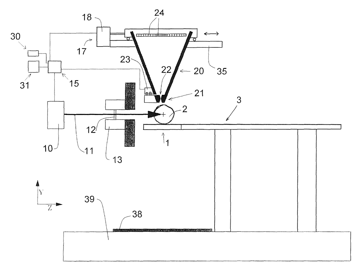
[0131]With reference to FIG. 1 an example of a proton radiation therapy installation adapted to subject a target to irradiation by a proton radiation beam according to the invention will be discussed below. It is noted that the invention equally applies to radiation installation emitting beams with other hadrons, e.g. carbon-ions.

[0132]The installation comprises a target support 1 configured to support, preferably immobilize, a target 2. In this example the target support is a patient head support for supporting the head of a patient or a phantom representing a human head. The head support here forms part of a human patient table 3 adapted to support the human patient (not shown) inclusive the head.

[0133]For example the target 2 is a 20 centimeter diameter sphere of brain tissue according to ICRU specifications.

[0134]The installation comprises a proton radiation apparatus 10 adapted to emit a pencil type proton radiation beam 11 along a beam axis (Z-axis) to irradiate the target 2 s...


PUM


Abstract

A hadron radiation installation adapted to subject a target to irradiation by a hadron radiation beam includes a target support configured to support, preferably immobilize, a target; a hadron radiation apparatus adapted to emit a hadron radiation beam along a beam axis to irradiate the target supported by the target support, the radiation beam penetrating into the target. The radiation apparatus has a control system at least comprising a beam penetration depth control allowing at least to control and vary the penetration depth of the radiation beam into the target. The installation has a radiation beam range sensor device adapted to determine the penetration depth of said radiation beam into the target, where the range sensor device includes a gamma camera responsive to prompt gamma rays that are emitted while the hadron radiation beam penetrates into the target.

Description

CROSS-REFERENCE TO RELATED APPLICATIONS[0001]This application is the National Stage of International Application No. PCT / NL2012 / 050719 filed Oct. 12, 2012, which claims the benefit of Netherlands Application No. 2007596, filed Oct. 14, 2011, the contents of which is incorporated by reference herein.FIELD OF THE INVENTION[0002]The present invention relates to the field of hadron radiation therapy.BACKGROUND OF THE INVENTION[0003]In the field of radiation therapy, e.g. for the treatment of tumors, it is understood that hadron radiation therapy (notably with protons or ions, such as carbon-ion therapy) offers significant advantages over X-ray or gamma ray therapies. In general hadron radiation therapy is an upcoming cancer treatment in which a hadron beam is used for irradiation. The number of hadron radiation therapy centers, mainly equipped with a proton radiation therapy installation, is growing rapidly and world wide over 50000 patients have been treated up to now.[0004]The dominan...

Claims


Application Information

Patent Timeline
Patent Type & Authority Patents(United States)
IPC IPC(8): A61N5/10G01T1/29
CPCA61N5/1067A61N5/1043A61N5/1048A61N5/1071A61N5/1075A61N5/1084G01T1/2935A61N2005/1052A61N2005/1076A61N2005/1087
Inventor BEEKMAN, FREDERIK JOHANNESBOM, VICTOR ROBERT
Owner TECH UNIV DELFT
Why Eureka
Try Eureka