Secure display device with twisted nematic liquid crystal matrix

a liquid crystal matrix and display device technology, applied in static indicating devices, instruments, non-linear optics, etc., can solve the problems of white screen, complete loss of equipment, and disruption of screen reconfigurations, so as to avoid hampering the pilot and avoid the effect of being presen

Active Publication Date: 2017-07-18
THALES SA
View PDF7 Cites 0 Cited by
  • Summary
  • Abstract
  • Description
  • Claims
  • Application Information

AI Technical Summary

Benefits of technology

[0015]The device according to the invention does not present these drawbacks. It makes it possible to force a black display on an LCD screen of twisted nematic type even if the latter is no longer controlled after, for example, a failure of the row drivers or of the column drivers. In the case of use of a dual screen, the device according to the invention also makes it possible to keep the second display operational without the pilot being hampered by the failed display that has become white. Thus, neither the system nor the pilot has to be concerned with the failure of the LCD. The device according to the invention therefore has a dual action: to not present an erroneous image and to avoid hampering the pilot.

Problems solved by technology

The drawback of this technology is that it naturally presents a white screen that is said to be “normally white” when the latter is defective or uncontrolled.
So as to restore a black screen, the failure of this type of screen results either in the automatic switching off of the light box which lights the matrix so as to restore a black screen, or the manual switching off of the equipment by the pilot.
This switching off results in the complete loss of the equipment.
This outcome is highly detrimental in the case of a dual display presenting two different and independent display types because it causes the loss of the second display, thus disrupting the screen reconfigurations needed to satisfy the aircraft certification and safety constraints.

Method used


Image

  • Secure display device with twisted nematic liquid crystal matrix
  • Secure display device with twisted nematic liquid crystal matrix
  • Secure display device with twisted nematic liquid crystal matrix

Examples


Embodiment Construction

[0038]Hereinafter, the same terms as previously have been adopted to designate the main elements of a display device.

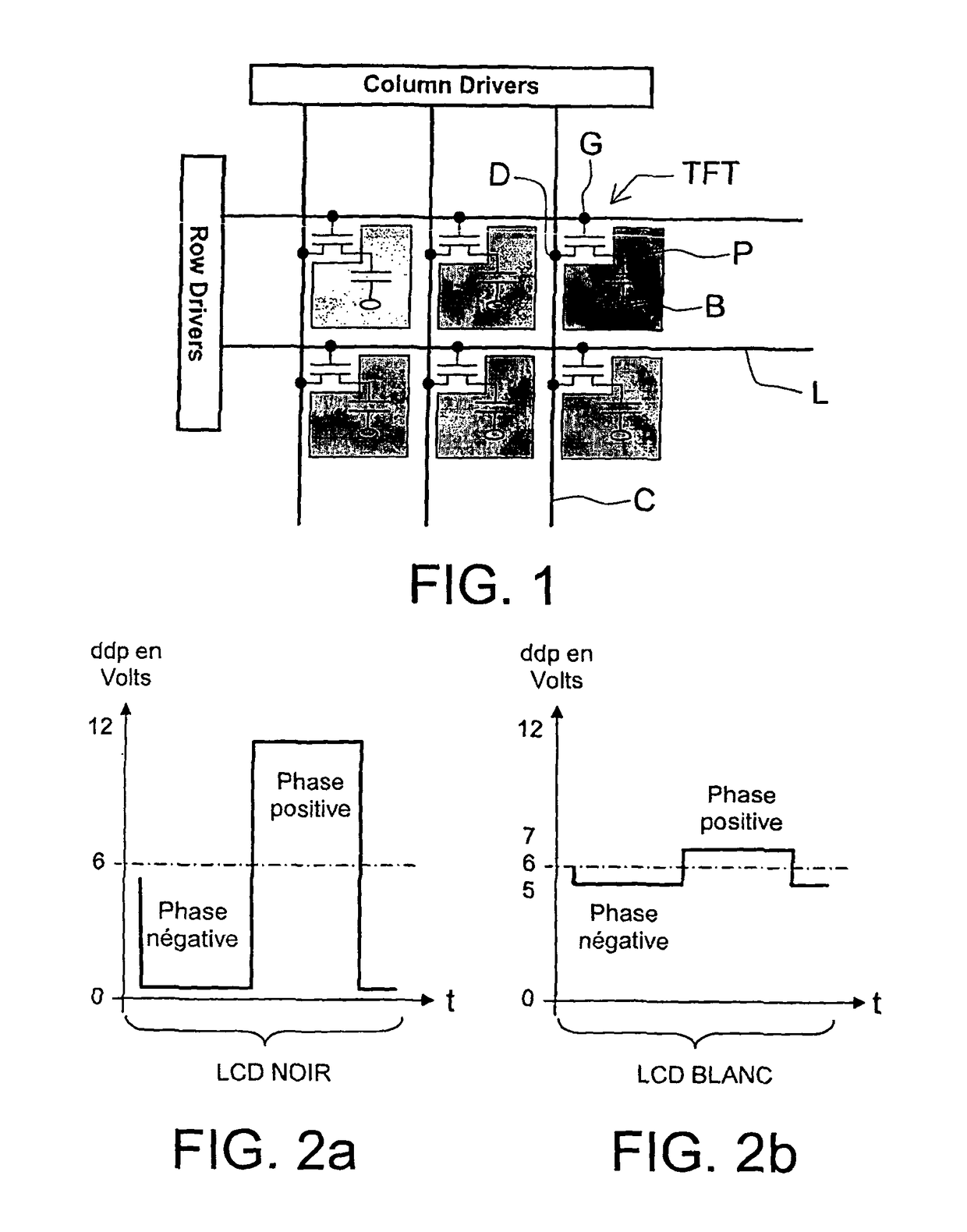
[0039]The display device according to the invention conventionally comprises an active liquid crystal matrix of twisted nematic type comprising:[0040]a first set of pixels, a first set of rows and of columns, a first electronic control device and first means for monitoring or detecting the correct operation of the first electronic control device;[0041]each pixel being controlled by a transistor comprising a source, a drain and a gate, the gate being linked to a row, the drain to a column and the source to the control electrode of the pixel;[0042]the voltage applied to each control row being either a switch-on voltage VG_on sufficient to switch on the transistors, or a switch-off voltage VG_off sufficient to switch off the transistors;[0043]the GMA voltage applied to each column being dependent on the predetermined optical transmission of the pixel.

[0044]The display de...


PUM

PropertyMeasurementUnit
voltageaaaaaaaaaa
voltageaaaaaaaaaa
voltageaaaaaaaaaa

Abstract

The general field of the invention is that of the display devices that comprise an active liquid crystal matrix of twisted nematic type. The matrix comprises a set of pixels, a set of rows and of columns and an electronic control device. Each pixel is controlled by a transistor. The voltage applied to each control row is either a switch-on voltage VG_on sufficient to switch on the transistors, or a switch-off voltage VG_off sufficient to switch off the transistors. The voltage applied GMA to each column is dependent on the predetermined optical transmission of the pixel. The display device comprises means for detecting the correct operation of the electronic control device. In case of detection of incorrect operation, the display device comprises cut-off means arranged to force to zero the switch-off voltages VG_off of the rows and the GMA voltages of the columns, so that the transmission of all the pixels of the first set is minimum.

Description

BACKGROUND OF THE INVENTION[0001]1. Field of the Invention[0002]The field of the invention is that of cockpit displays in which the display devices comprise a liquid crystal matrix, also called “LCD”, standing for “Liquid Crystal Display”. These display screens are nowadays tilted in all types of fixed or revolving wing aircraft in both civilian and military domains.[0003]2. Description of the Prior Art[0004]An LCD screen operates on the principle of matrix addressing. As can be seen in FIG. 1, the LCD screen is made up of coloured individual pixels organized in a matrix. Six pixels P are represented in FIG. 1 with different shades of grey representing the colours of the pixels. Each pixel P is made up of a thin thickness of liquid crystal contained between two electrodes, a first so-called control electrode and a second, back electrode B, called “backplane”, common to all the matrix and symbolized by ellipses in FIG. 1. The potential difference or ddp between the electrodes is cont...

Claims


Application Information

Patent Timeline
Patent Type & Authority Patents(United States)
IPC IPC(8): G02F1/13G09G3/36
CPCG02F1/1309G09G3/3648G09G3/3666G09G3/3696G09G2310/0245G09G2330/08G09G2330/10G09G2330/12
Inventor CANAL, LAURENTSANTIAGO, DORIAN
Owner THALES SA
Why Eureka
Try Eureka