
Connector cover, connector and connector module

a technology of connector module and connector cover, which is applied in the manufacture of contact member cases/bases, coupling device connections, electrical devices, etc., can solve the problems of memory module generating a significant amount of heat, the cover of the connector may crack, and the motherboard may be slightly bent, so as to prevent the connector from warping or cracking

Active Publication Date: 2017-07-18
GIGA BYTE TECH CO LTD
View PDF20 Cites 6 Cited by
  • Summary
  • Abstract
  • Description
  • Claims
  • Application Information

AI Technical Summary

Benefits of technology

The invention provides a connector cover that prevents the connector from getting bent or cracked. The cover has a base that leans against the connector, and the cover's top surface also leans against the connector. This design increases the strength of the connector module. The cover also has a concave where the fixing member of the connector leans, which prevents the cover from easily pulling away from the connector. Additionally, the cover's neighboring walls prevent bending or bending upward or downward, making the connector more resistant to bending. If the connector module is attached to a motherboard, it helps prevent the motherboard from bending.

Problems solved by technology

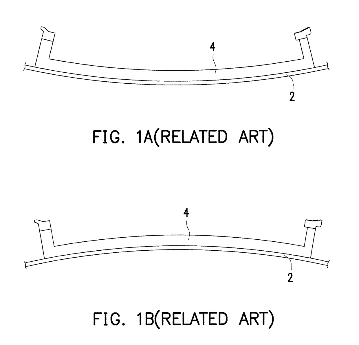
Since the wires are not evenly distributed, the motherboard may be slightly bent during the manufacturing process of the motherboard due to different average thermal expansion coefficients at different parts of the motherboard.
Taking memory module as an example, a memory module may generate a significant amount of heat when it is operated in a high performance mode.
However, since this kind of memory module is heavier, the cover of the connector may crack when the memory module is inserted into the connector of the motherboard.

Method used


Image

  • Connector cover, connector and connector module
  • Connector cover, connector and connector module
  • Connector cover, connector and connector module

Examples


Embodiment Construction

[0031]Reference will now be made in detail to the present preferred embodiments of the invention, examples of which are illustrated in the accompanying drawings. Wherever possible, the same reference numbers are used in the drawings and the description to refer to the same or like parts.

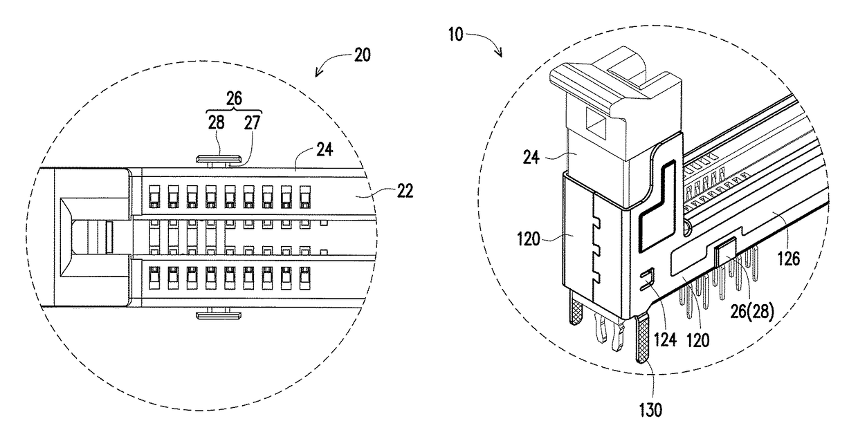
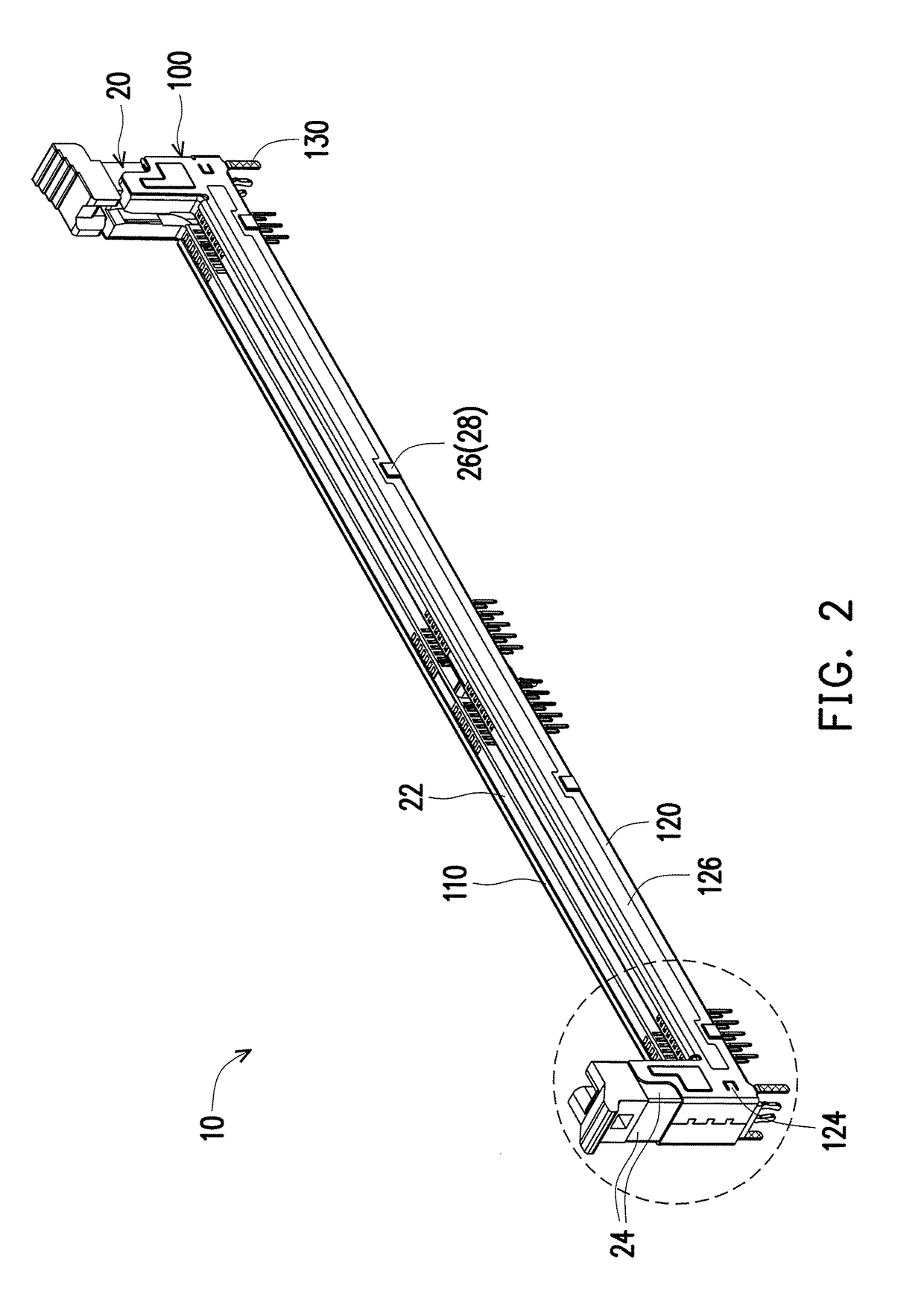
[0032]FIGS. 2 and 3 are schematic views illustrating a connector module according to an embodiment of the invention from different perspectives. Referring to FIGS. 2 and 3, a connector module 10 of this embodiment includes a connector 20 and a connector cover 100. In this embodiment, the connector 20 is described as a memory module connector, for example. However, the type of the connector 20 is not limited thereto. A connector cover 100 covers the connector 20 to provide the connector module 10 with a preferable structural strength. Besides, through a special mechanical configuration, the connector cover 100 of the connector module 10 of this embodiment may lean against the connector 20 and prevent ...


PUM


Abstract

A connector cover is adapted to cover a connector. A fixing member of the connector protrudes from a connector lateral and includes a base portion and a top board located on the base portion. The top board and the base portion form a T shape pillar. The connector cover includes four cover laterals, and one of the cover laterals includes a concave. A position of the concave located on the cover lateral corresponds to a position of the fixing member located on the connector lateral, and a width of the concave is close to a width of base portion. When the connector cover is assembled to the connector, the cover laterals lean against the connector laterals. The base portion is located in the concave and walls of the cover lateral besides the concave is near or lean against the base portion. A connector and a connector module are further provided.

Description

CROSS-REFERENCE TO RELATED APPLICATION[0001]This application claims the priority benefit of Taiwan application serial no. 105101664, filed on Jan. 20, 2016. The entirety of the above-mentioned patent application is hereby incorporated by reference herein and made a part of this specification.BACKGROUND OF THE INVENTION[0002]1. Field of the Invention[0003]The invention relates to a connector cover, a connector and a connector module, and particularly relates to a connector cover and a connector module capable of reinforcing a strength of a connector providing better fixing effect of an expansion card.[0004]2. Description of Related Art[0005]Generally speaking, a motherboard is manufactured by alternately stacking a plurality of dielectric layers and a plurality of wire layers, and a plurality of electronic components and slots are disposed on the motherboard. Since the wires are not evenly distributed, the motherboard may be slightly bent during the manufacturing process of the mothe...

Claims


Application Information

Patent Timeline
Patent Type & Authority Patents(United States)
IPC IPC(8): H01R13/6581H01R13/516H01R12/73H01R43/18
CPCH01R13/516H01R12/737H01R43/18H01R12/721
Inventor LAI, CHIH-MINGKAO, YUNG-SHUNCHIANG, CHUNG-WEI
Owner GIGA BYTE TECH CO LTD
Learn More