
Device and method for producing injection-molded parts which comprise different components

a technology of injection molding and plastic parts, which is applied in the direction of thin material processing, domestic applications, other domestic articles, etc., can solve the problems of difficult removal and further processing of components, and the injection molding device is not intended for the production of plastic parts, so as to simplify the precise positioning of plastic parts, the effect of easy and fast production

Active Publication Date: 2017-08-01
FOBOHA
View PDF12 Cites 1 Cited by
  • Summary
  • Abstract
  • Description
  • Claims
  • Application Information

AI Technical Summary

Benefits of technology

The invention is an improved injection-molding device and method for the production of plastic parts with multiple components. This device allows for easy and fast production, simplifies precise positioning of parts, and enables flexible and rapid production. The method involves producing sub-components of the plastic parts using halves of a center block, which can be quickly assembled without additional effort or changes in production steps. The tolerances of the parts can be reduced, resulting in high precision. The device is particularly suitable for the production of beverage package caps, where complex and expensive external assembly devices can be replaced with a cost-effective and reliable injection-molding solution.

Problems solved by technology

This injection-molding device is not intended for the production of plastic parts comprising a plurality of different plastic components.
Here, the different components are finished on different sides of the rotatable mold carrier element, which makes removal and further processing of the components more difficult.

Method used


Image

  • Device and method for producing injection-molded parts which comprise different components
  • Device and method for producing injection-molded parts which comprise different components

Examples


Embodiment Construction

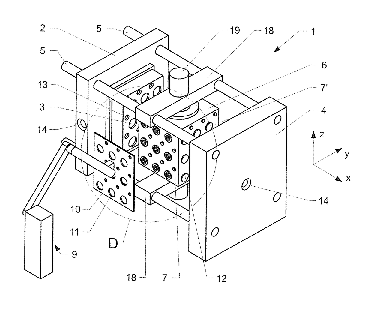
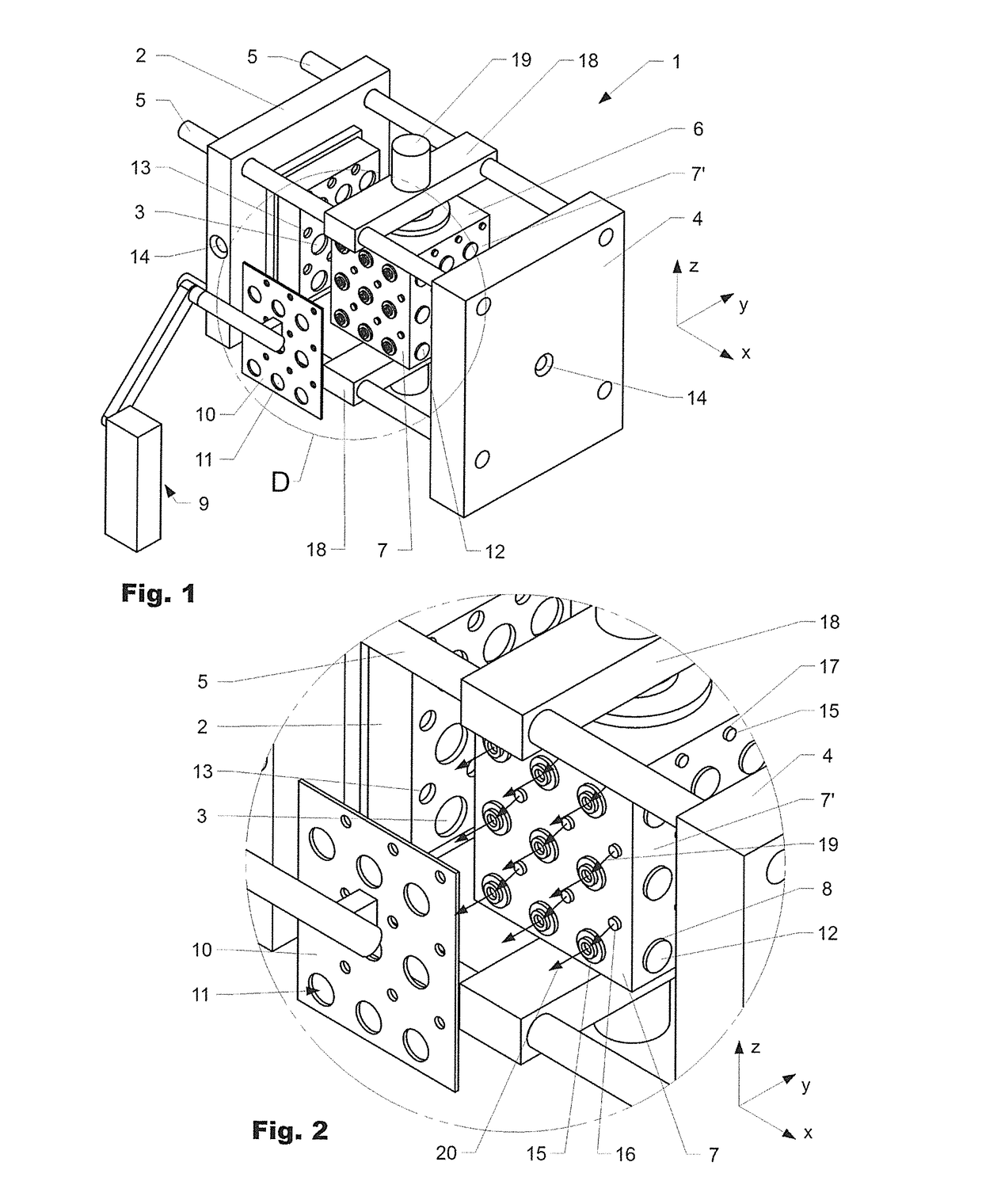
[0031]An injection-molded device 1, which has a first mold mounting plate 2 with first cavity halves 3 and a second mold mounting plate 4 with second cavity halves lying opposite thereto, is shown in FIG. 1. The mold mounting plates 2 and 4 are connected to one another by tie bars 5 in such a way that the second mold mounting plate 4 can be slid relative to the first mold mounting plate 2 in a first direction along the longitudinal axis of the injection-molding device; in the direction x according to FIG. 1. A center block 6, which can be rotated about an axis z and can be slid in the first direction, is provided between the first and the second mold mounting plate. The center block has four side surfaces 7, wherein center cavity halves 8 and third cavity halves 17 are attached to one side surface. The center block 6 is rotatably held on the upper and lower tie bars 5 by means of an upper and a lower holding device 18. A rotating device 19 is provided on the upper holding device 18 ...


PUM

PropertyMeasurementUnit
weightaaaaaaaaaa
areaaaaaaaaaaa
flexibleaaaaaaaaaa

Abstract

The invention relates to a device and a method for producing plastic moldings from at least two different sub-elements (15; 16) that includes first and second mold halves (3) and a rotatable center block (6) with center and third mold halves (8; 17) interposed therebetween. The center and third mold halves define first and second parting planes with the first and second mold halves. First cavities are defined in the first parting plane, into which a first plastic component is introduced to produce preforms (12). When the first parting plane is opened, the performs (12) remain on the center mold halves (8) and are brought into the second parting plane when the center block (6) is rotated, in which second parting plane second cavities are at least partially defined by the preforms (12), into which a second plastic component is introduced and first sub-elements (15) are produced. Second sub-elements (16) are produced in the additional cavities. When the second parting plane is opened, the sub-elements (15; 16) remain on the center and third mold halves (8) and are rotated into a lateral assembly position when the center block (6) is rotated.

Description

BACKGROUND OF THE INVENTION[0001]Field of the Invention[0002]The present invention relates to a method and a device for injection-molding and assembling plastic parts comprising a plurality of plastic components, in particular an injection-molding device with a rotatable cube tool as claimed in the pre-characterizing clause of the independent claims.[0003]Discussion of Related Art[0004]Injection-molding devices for injection molding with one or more rotating center mold parts, usually in the form of a cube, are known from the prior art. These are used, for example, for the efficient production of multi-component plastic parts.[0005]An injection-molding machine with two parting planes and a turning system which is arranged between a fixed and a moving mold mounting plate and has a center rotating block with cavity halves on the side surfaces is presented in EP1155802. The center rotating block is retained between the mold mounting plates by a lower and an upper holding device and can...

Claims


Application Information

Patent Timeline
Patent Type & Authority Patents(United States)
IPC IPC(8): B29C45/04B29C45/00B29C45/14B29C45/16B29L31/56
CPCB29C45/1418B29C45/006B29C45/045B29C45/1628B29L2031/565Y10T428/1352
Inventor ARMBRUSTER, RAINER
Owner FOBOHA
Learn More