Spring member mounting structure of seat frame for vehicle

a technology of seat frame and spring member, which is applied in the direction of vehicle seats, vehicle components, vehicle arrangements, etc., can solve the problem of inhibiting the increase in cos

Active Publication Date: 2017-08-01
TOYOTA BOSHOKU KK
View PDF11 Cites 11 Cited by
  • Summary
  • Abstract
  • Description
  • Claims
  • Application Information

AI Technical Summary

Benefits of technology

[0007]An object of the present invention is to provide a spring member mounting structure, which does not need to implement special processing to a connecting rod such as a rear pipe or a front pipe, and is capable of mounting a spring member such as an S spring without producing a misassembly.
[0009]According to the first aspect, an end of the extension portion of the cover member abuts on the connecting rod to position the spring member. Thus, there is only one position where the spring member, which abuts on the end of the extension portion of the cover member, abuts on and is engaged with the connecting rod, which can prevent a misassembly. Further, there is no need to implement special processing, e.g., providing a diameter-expanding portion or the like on the connecting rod, so an increase in cost can be inhibited.
[0011]According to the second aspect, the extension portion, which includes the ends, extends at a prescribed length to be in contact with or close to the outer peripheral surface of the connecting rod. Therefore, even under a force in the width direction from the engaging portion of the spring member, deformation of the extension portion is small, and the spring member can be firmly positioned relative to the connecting rod.
[0013]According to the third aspect, the engaging portions of the spring member are provided at both ends in the width direction, and respectively abut on the extension portions of the cover members provided at the connecting portions of the side frames on both sides and the connecting rod so as to be positioned. Thus, the positioning of the spring member relative to the connecting rod is more reliable, and can further reduce the possibility of a misassembly.

Problems solved by technology

Further, there is no need to implement special processing, e.g., providing a diameter-expanding portion or the like on the connecting rod, so an increase in cost can be inhibited.

Method used


Image

  • Spring member mounting structure of seat frame for vehicle
  • Spring member mounting structure of seat frame for vehicle
  • Spring member mounting structure of seat frame for vehicle

Examples


Embodiment Construction

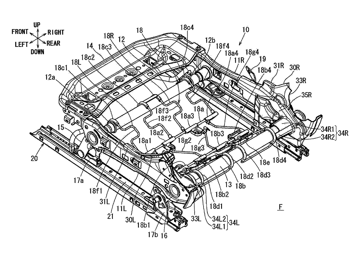
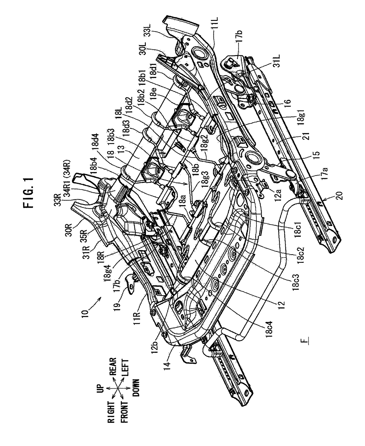
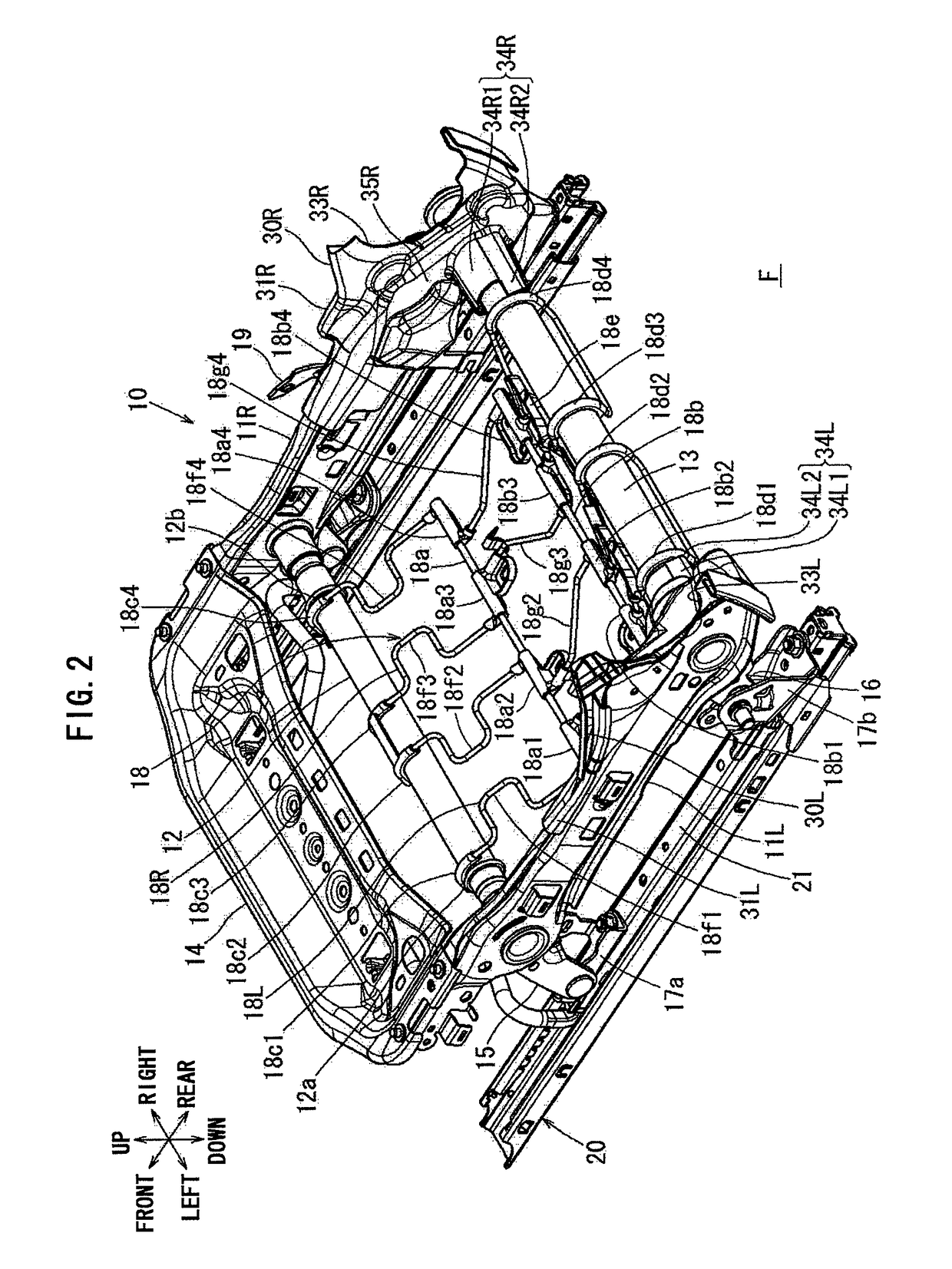
[0023]FIGS. 1-6 show an embodiment of the present invention. The embodiment shows an example in which the present invention is applied in a cushion frame for an automobile (hereinafter referred to as the cushion frame). In the various figures, the various directions of the cushion frame are indicated by arrows. In the following description, the depiction of the direction is given by taking these directions as references. The cushion frame 10 of the present embodiment is mounted with a back frame (not shown) in the rear of the cushion frame via a recliner (not shown) so as to constitute a seat frame. Since the back frame is a well known structure, the description thereof is omitted, and the cushion frame 10 is described.

[0024]The cushion frame 10 has, on left and right sides thereof, side frames 11L, 11R extending along a front-and-rear direction. The side frames 11L, 11R, which are substantially rectangular plate-shaped stamped parts, extend longitudinally in the front-and-rear dire...


PUM


Abstract

The present invention relates to a spring member mounting structure, which is a structure for mounting a spring member on a cushion frame connecting side frames by use of a rear pipe. The spring member has rear clipping portions engaged with the rear pipe. Cover members, which are provided at seat central sides of connecting portions of the side frames and the rear pipe, have extension portions extending toward the seat central sides. The rear clipping portions abut on ends of the seat central sides of the extension portions, and are mounted to the rear pipe by width direction positioning of the spring member.

Description

INCORPORATION BY REFERENCE[0001]The disclosure of Japanese Patent Application No. 2014-091102 filed on Apr. 25, 2014 including the specification, drawings and the abstract is incorporated herein by reference in its entirety.BACKGROUND OF THE INVENTION[0002]1. Field of the Invention[0003]The present invention relates to a structure for mounting a spring member supporting a seat occupant on a seat frame for a vehicle.[0004]2. Description of Related Art[0005]The seat frame for a vehicle is provided with a spring member such as an S spring to support the seat occupant, and the spring member is positioned and mounted relative to the seat frame. In the seat frame for a vehicle as described in Japanese Patent Application Publication No. 2002-225600 (JP 2002-225600 A), a portion of a rear pipe or a front pipe connecting a pair of left and right side frames is diameter-expanded by a hydroforming process to provide a large-diameter portion, such that both ends in a width direction of a retain...

Claims


Application Information

Patent Timeline
Patent Type & Authority Patents(United States)
IPC IPC(8): B60N2/54B60N2/70B60N2/72B60N2/68
CPCB60N2/546B60N2/68B60N2/7058B60N2/7094B60N2/72
Inventor MATSUI, HAYATO
Owner TOYOTA BOSHOKU KK
Why Eureka
Try Eureka