Quantum mechanical measurement device

a mechanical measurement and quantum mechanical technology, applied in wave based measurement systems, instruments, reradiation, etc., can solve problems such as drift and heading errors, emitters that do not respond to modulation, and complicating the operation of magnetometers

Active Publication Date: 2017-08-08
GEOMETRICS
View PDF24 Cites 40 Cited by
  • Summary
  • Abstract
  • Description
  • Claims
  • Application Information

AI Technical Summary

Problems solved by technology

As a result, the details of the modulation affect the magnetic field measurement, leading to drift and heading error.
Furthermore, a semiconductor laser emitter does not respond to the modulation immediately, because of its thermal time constants.
These phase shifts complicate the operation of the magnetometer.

Method used


Image

  • Quantum mechanical measurement device
  • Quantum mechanical measurement device
  • Quantum mechanical measurement device

Examples


example

[0026

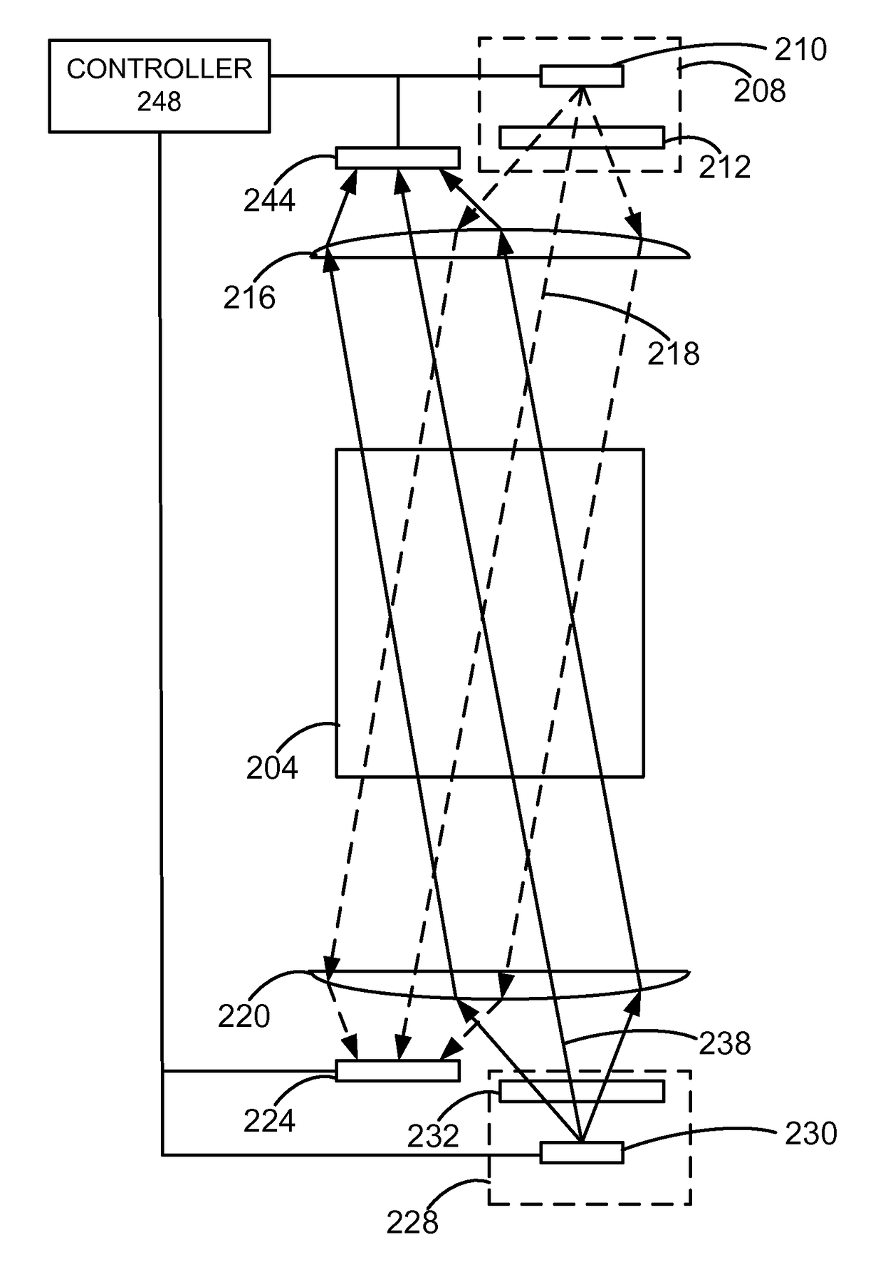
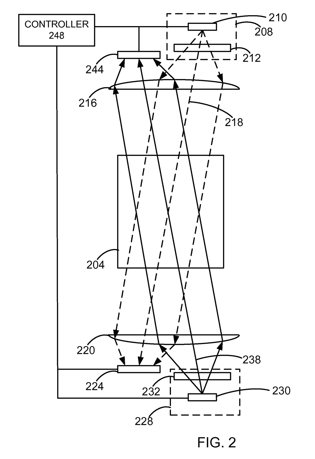
[0027]FIG. 2 is a schematic diagram of an example of an embodiment of the invention. In this example, a spin ensemble 204 holding a cesium atomic vapor is provided. A first light source 208 is provided, comprising a first laser diode 210 and a first polarizer 212, so that the first light source 208 provides a polarized light. A first lens 216 is placed in a first optical path 218 between the first light source 208 and the spin ensemble 204. A second lens 220 is placed on an opposite side of the spin ensemble 204 from the first lens 216 along the first optical path 218. A first detector 224 is placed on an opposite side of the second lens 220 from the spin ensemble 204 along the first optical path 218. A second light source 228 is provided, comprising a second laser diode 230 and a second polarizer 232, so that the second light source 232 provides a polarized light. The second lens 220 is placed in a second optical path 238 between the second light source 228 and the spin ensemb...


PUM

PropertyMeasurementUnit
Larmor precession frequencyaaaaaaaaaa
resonance frequencyaaaaaaaaaa
quantum mechanical measurementaaaaaaaaaa

Abstract

A quantum mechanical measurement device is provided. A spin ensemble is provided. A first light source provides a first light at a first wavelength, wherein the first light source is positioned to provide light into the spin ensemble. A detector is positioned to detect light from the spin ensemble. A modulator modulates absorption of the first light from the first light source by the spin ensemble at a frequency greater than a Larmor frequency of the spin ensemble.

Description

CROSS REFERENCE TO RELATED APPLICATIONS[0001]This application claims priority under 35 U.S.C. §119(e) from U.S. Provisional Application No. 61 / 601,883, entitled “LASER-BASED ATOMIC MAGNETOMETERS”, filed Feb. 22, 2012, and naming Smith et al. as inventors, which is incorporated by reference in its entirety for all purposes.BACKGROUND OF THE INVENTION[0002]Field of the Invention[0003]The present invention relates to the field of magnetometers. More specifically, the present invention relates to magnetometers based on spin ensembles, for example, alkali vapor cells.[0004]Description of the Related Art[0005]Magnetometers are used to measure the strength and direction of a magnetic field. They can be useful in measuring minute changes in the Earth's magnetic field that allow users to identify geological conditions under the Earth's surface, such as the location of oil and mineral deposits, as well as other conditions.[0006]A magnetometer that uses a cesium atomic vapor is described in U....

Claims


Application Information

Patent Timeline
Patent Type & Authority Patents(United States)
IPC IPC(8): G01N24/00G01R33/26
CPCG01N24/006G01R33/26
Inventor SMITH, KENNETH R.KIERSNOWSKI, KRZYSZTOF
Owner GEOMETRICS
Why Eureka
Try Eureka