Techniques for guide-wire based advancement of a tool

a technology of guide wires and tools, applied in the field of valve and chordae tendineae repair, can solve the problems of reducing cardiac output, increasing total stroke volume, and ending weakening of the left ventricl

Active Publication Date: 2017-08-15
VALTECH CARDIO LTD
View PDF828 Cites 95 Cited by
  • Summary
  • Abstract
  • Description
  • Claims
  • Application Information

AI Technical Summary

Benefits of technology

[0019]In some applications of the present invention, the adjustment mechanism comprises a reversible locking mechanism which facilitates bidirectional rotation of the spool in order to effect both tensioning and relaxing of the repair chord. That is, the spool is wound in one direction in order to tighten the repair chord, and in an opposite direction in order to slacken the repair chord. Thus, the spool adjustment mechanism facilitates bidirectional adjustment of the repair chord.
[0059]In an application, sliding the chord-engaging element distally out of the housing includes facilitating transitioning of the chord-engaging element from a generally straight state into a helical state.
[0076]In an application, advancing the chord-engaging element out of the opening of the housing includes facilitating a transition of the chord-engaging member from a generally straight state into a helical state.

Problems solved by technology

Mitral regurgitation of blood from the left ventricle into the left atrium results in increased total stroke volume and decreased cardiac output, and ultimate weakening of the left ventricle secondary to a volume overload and a pressure overload of the left atrium.

Method used


Image

  • Techniques for guide-wire based advancement of a tool
  • Techniques for guide-wire based advancement of a tool
  • Techniques for guide-wire based advancement of a tool

Examples


Embodiment Construction

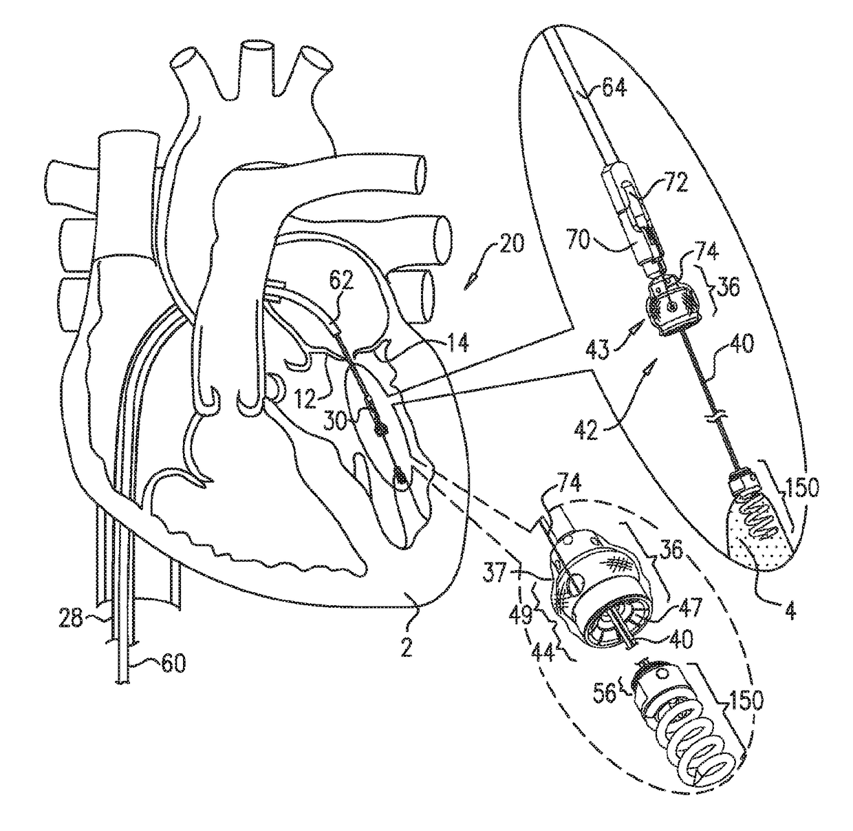
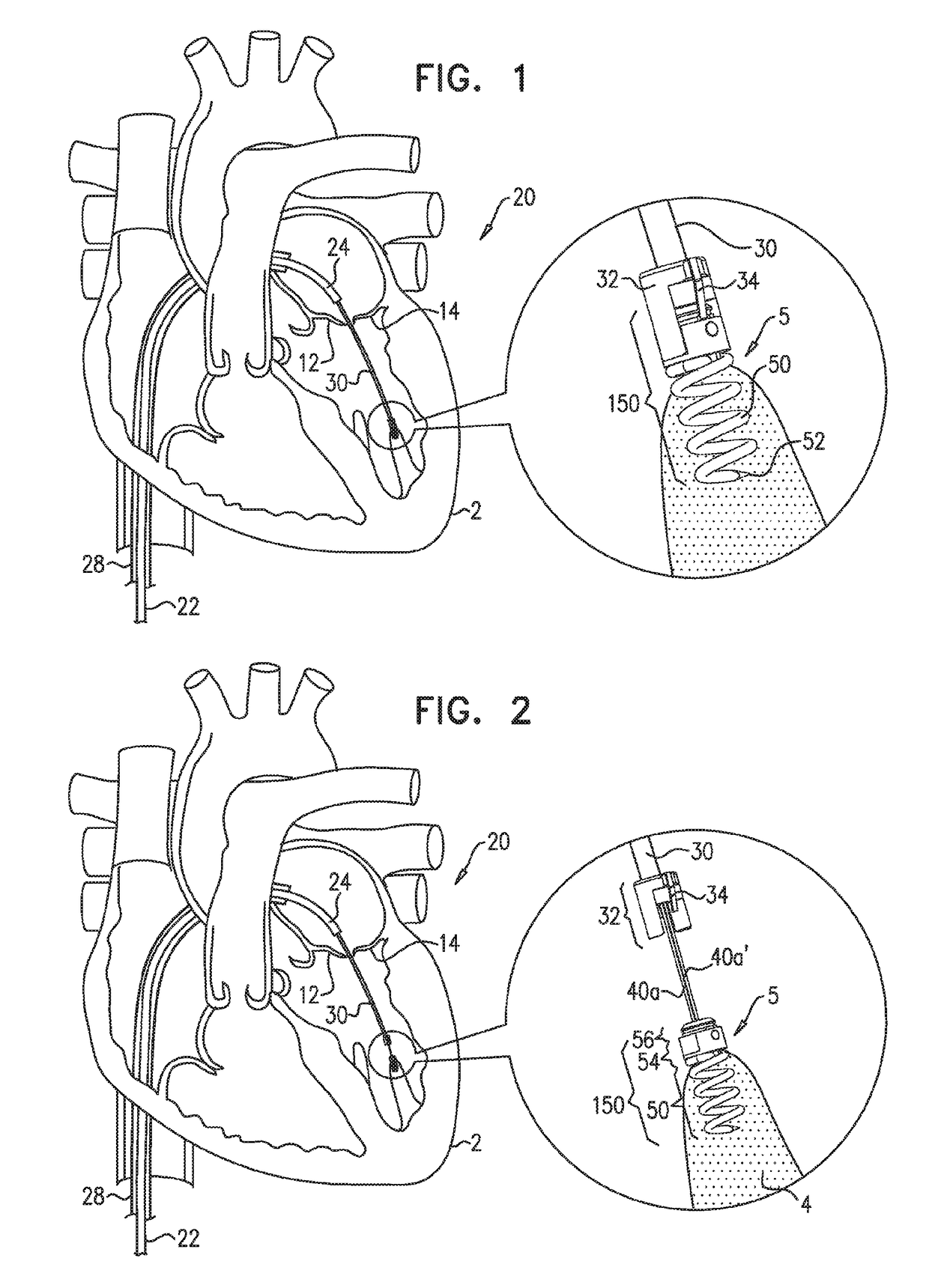
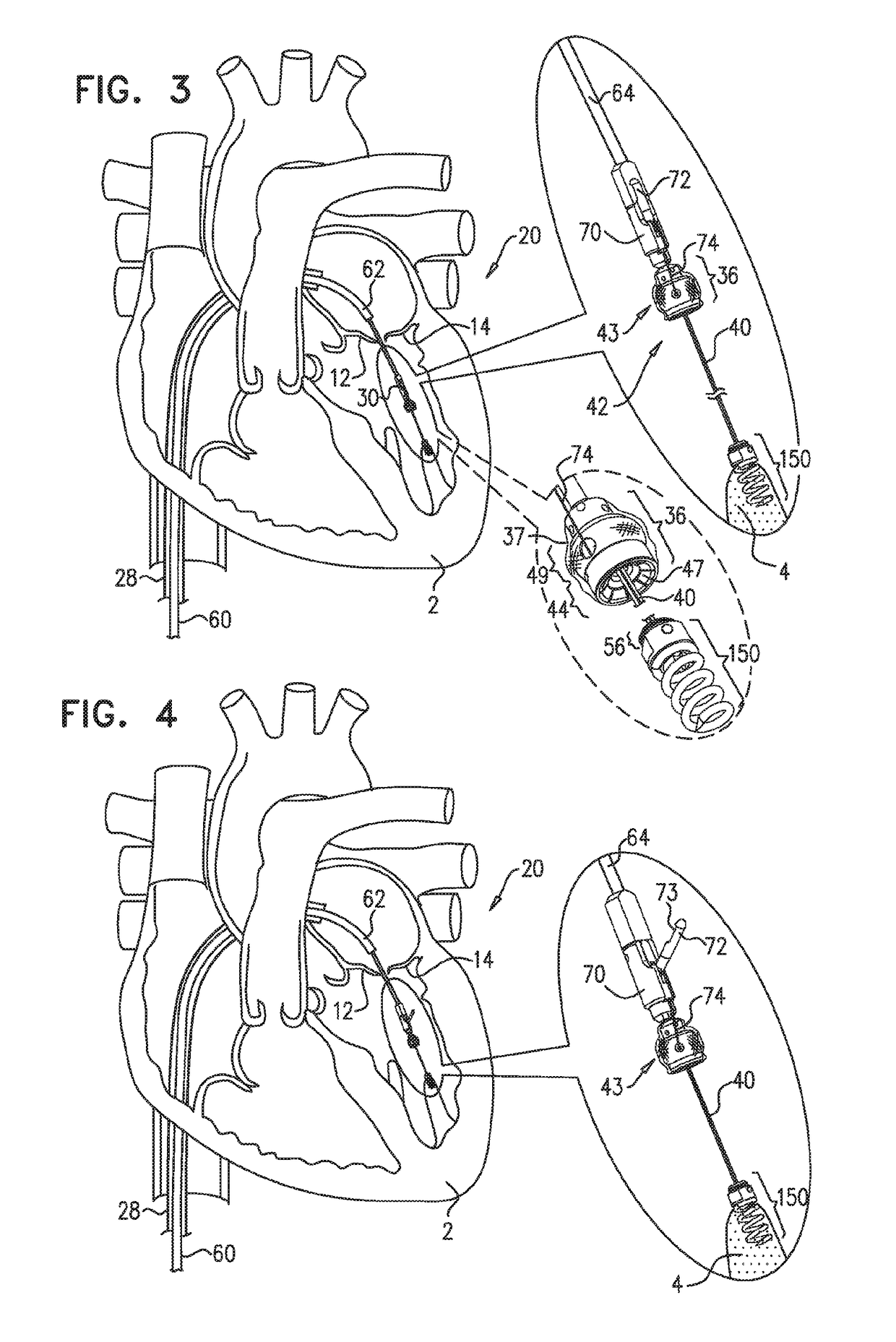
[0085]Reference is now made to FIGS. 1-2, which are schematic illustrations of a system 20 comprising a docking assembly 150 for implantation at a first implantation site 5 of a patient, in accordance with some applications of the present invention. As shown in FIG. 2, docking assembly 150 comprises a tissue-engaging element having (1) a distal portion comprising a tissue anchor 50 (e.g., a helical tissue anchor as shown by way of illustration and not limitation), and (2) a proximal portion comprising a docking platform 54, and at least one docking station 56. Thus, docking assembly 150 comprises (a) the distal portion which engages the tissue of the patient (i.e., the tissue-engaging element), and (b) the proximal portion which is coupled to docking station 56. At least one guide member, (e.g., a guidewire 40, shown in FIG. 2) is reversibly coupled to docking assembly 150 (e.g., by being looped around, or otherwise coupled to, a portion of assembly 150) so as to define first and se...


PUM


Abstract

Apparatus comprises: (A) a housing (248), percutaneously deliverable to a heart of a subject, slidable along a guidewire (242), and shaped to define at least one opening (249); (B) a guide member (250), percutaneously deliverable to the heart, percutaneously removable from the subject, couplable to the housing, and having: (i) a distal portion, comprising a chord-engaging element (252), configured to be percutaneously slidably coupled to and decouplable from at least one chordae tendineae (244), and (ii) a proximal portion, comprising a longitudinal element (251); and (C) a deployment tool, configured (i) to be reversibly coupled to a tissue anchor (50,280), (ii) to be slidably coupled to the longitudinal element of the guide member, and (iii) to anchor the tissue anchor to a papillary muscle (254) of the subject. Other embodiments are also described.

Description

CROSS-REFERENCES TO RELATED APPLICATIONS[0001]The present application claims priority from U.S. Provisional Patent application 61 / 733,979 to Reich et al., filed Dec. 6, 2012, and entitled “Techniques for guide-wire based advancement of a tool”; and is related to:[0002](a) International Application PCT / IL2011 / 000446 to Miller et al., entitled “Apparatus and method for guide-wire based advancement of a rotation assembly,” filed on Jun. 6, 2011 (which published as WO / 2011 / 154942);[0003](b) U.S. patent application Ser. No. 12 / 795,192 to Miller et al., entitled “A method for guide-wire based advancement of a rotation assembly,” filed on Jun. 7, 2010 (which published as US 2011 / 0301698, now U.S. Pat. No. 8,690,939);[0004](c) U.S. patent application Ser. No. 12 / 795,026 to Miller et al., entitled “Apparatus for guide-wire based advancement of a rotation assembly,” filed on Jun. 7, 2010 (which published as US 2011 / 0106245, now U.S. Pat. No. 8,940,042), which is a continuation-in-part of U.S....

Claims


Application Information

Patent Timeline
Patent Type & Authority Patents(United States)
IPC IPC(8): A61F2/24A61B17/3209A61B17/04A61M25/04A61M25/09
CPCA61F2/2427A61B17/0401A61B17/3209A61B2017/0409A61B2017/0443A61M25/04A61M25/09A61M2025/09183A61B2017/00247A61B2017/0441A61B2017/22042A61B2017/22047A61B2017/3488A61F2/2457A61F2/2466A61B2017/0464A61B2017/00243A61B2017/044
Inventor REICH, TALMILLER, ERAN
Owner VALTECH CARDIO LTD
Why Eureka
Try Eureka