
Fan assembly

a technology of fan assembly and spring, which is applied in the direction of pump installation, non-positive displacement fluid engine, liquid fuel engine components, etc., can solve the problems of reducing the friction force between the rails and runners, compromising the mechanism ability, and the body moving gradually closer, so as to achieve the effect of relatively low spring relaxation over the lifetime of the fan assembly

Inactive Publication Date: 2017-08-15
DYSON TECH LTD
View PDF486 Cites 2 Cited by
  • Summary
  • Abstract
  • Description
  • Claims
  • Application Information

AI Technical Summary

Benefits of technology

The present invention is a fan assembly with a brake and stop member connected to the base, which replaces the support members of the base. The brake and stop member are located on the upper surface of the base. The brake can slide relative to the base and is biased towards the stop member to resist movement of the body relative to the base. The brake is designed to allow for easy movement of the body and is enclosed to maintain a tidy appearance. The base also comprises control means for controlling the fan assembly. The technical effects include improved safety and ease of use.

Problems solved by technology

A problem associated with this mechanism for maintaining the body in a tilted position relative to the base is that, depending on the material from which the springs are formed, relaxation of the springs over time can cause the body to move gradually closer to the base, reducing the friction forces between the rails and the runners.
If this relaxation is severe, this can compromise the ability of the mechanism to maintain the body in a tilted position.

Method used


Image

  • Fan assembly
  • Fan assembly
  • Fan assembly

Examples


Embodiment Construction

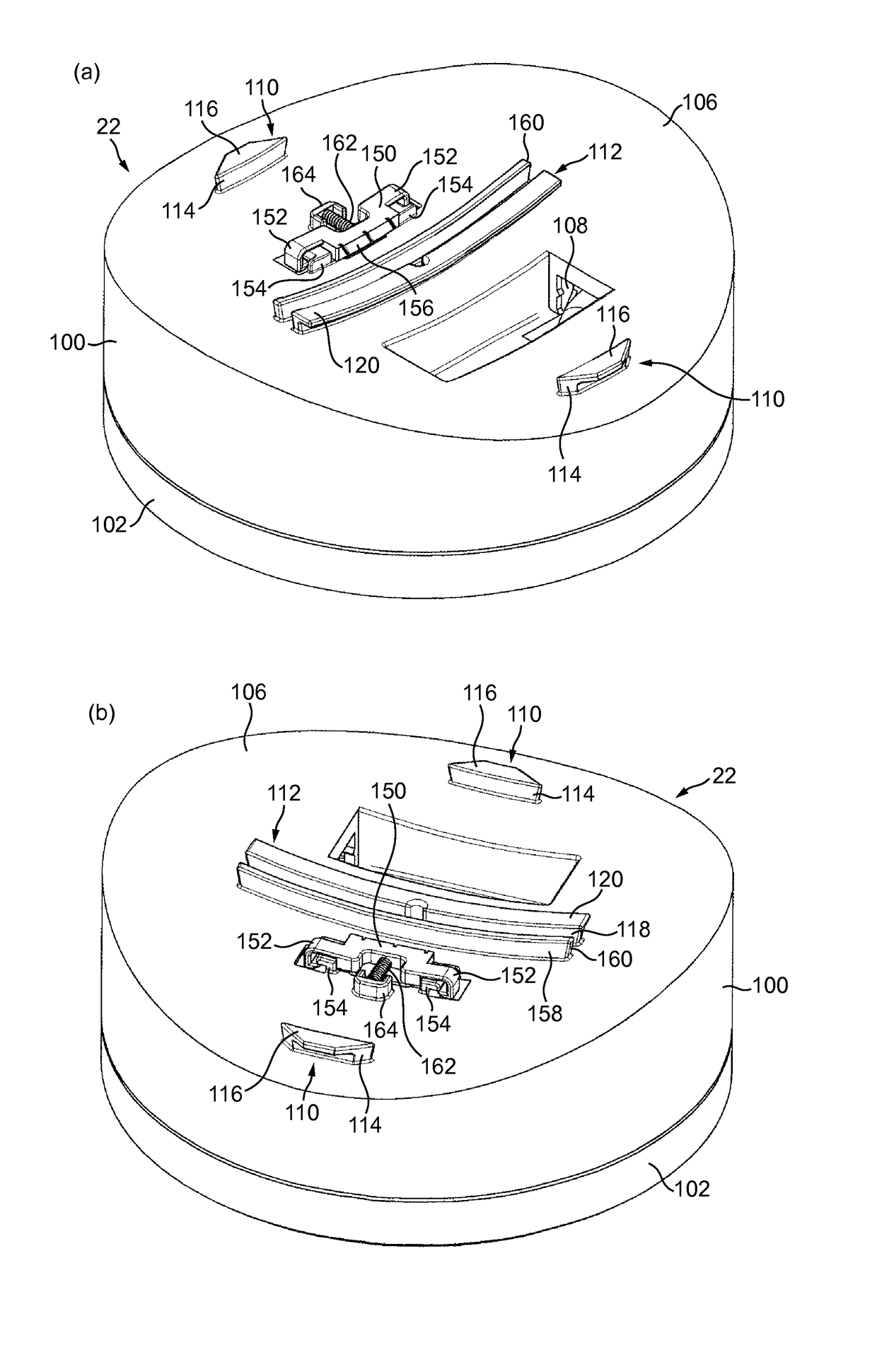
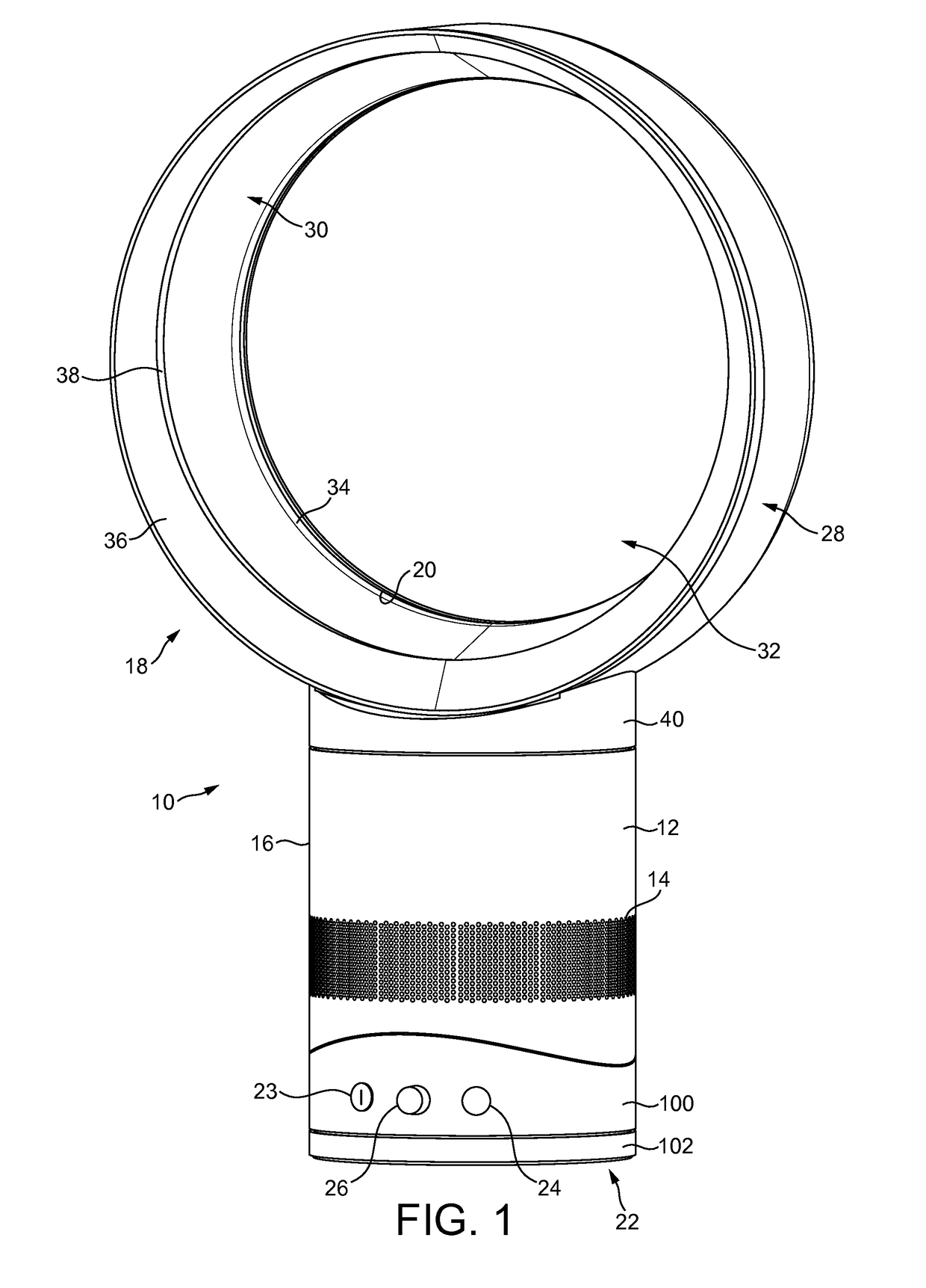
[0039]FIG. 1 is an external view of a fan assembly 10. The fan assembly 10 comprises a body 12 having an air inlet 14 in the form of a plurality of apertures formed in the outer casing 16 of the body 12, and through which a primary air flow is drawn into the body 12 from the external environment. An annular nozzle 18 having an air outlet 20 for emitting the primary air flow from the fan assembly 10 is connected to the upper end of the body 12. The body 12 is mounted on a base 22 so as to allow the body 12 to tilt relative to the base 22. The base 22 comprises a user interface for allowing a user to control the operation of the fan assembly 10. In this embodiment, the user interface comprises a plurality of user-operable buttons 23, 24 and a user-operable dial 26.

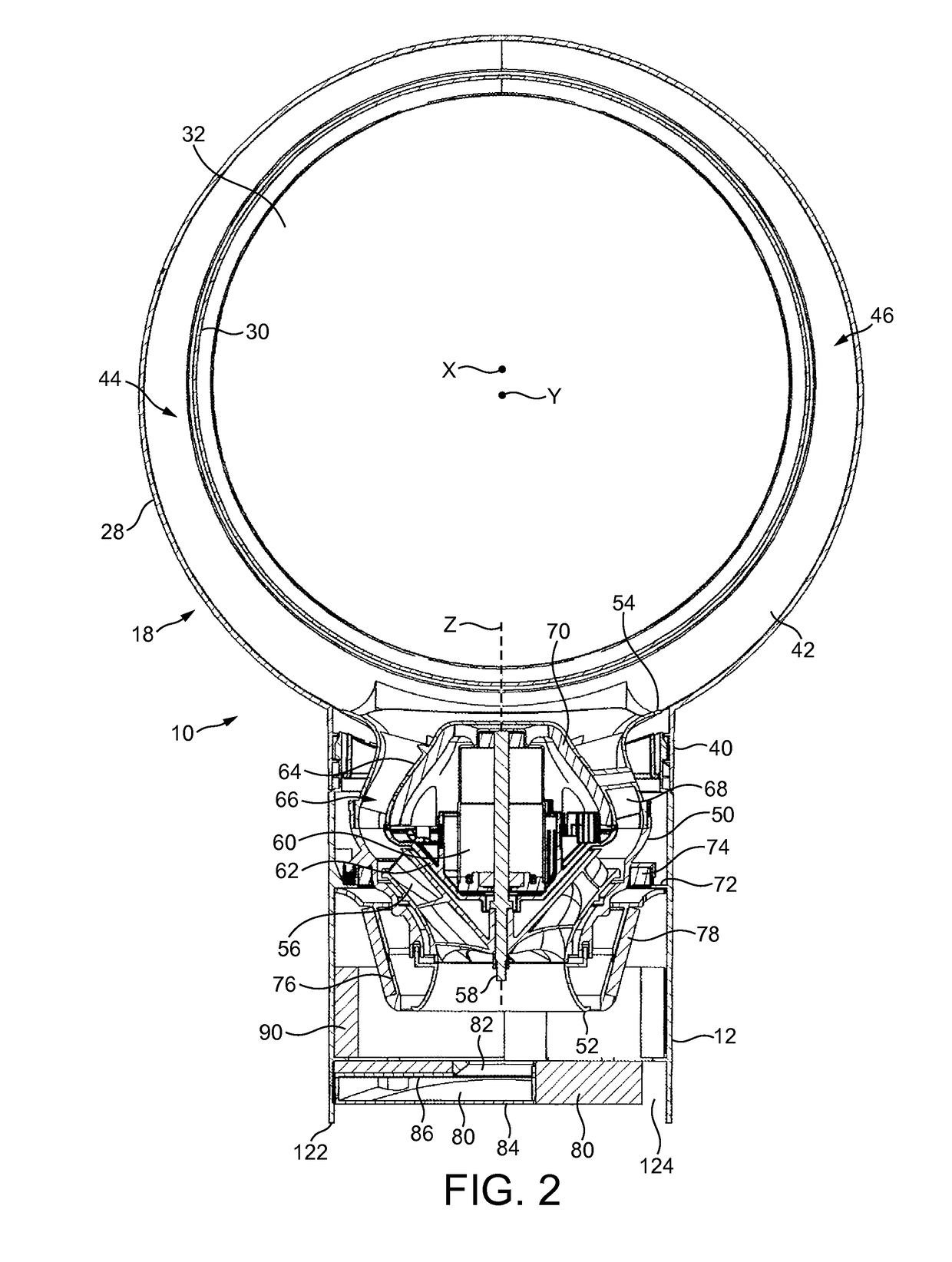
[0040]The nozzle 18 has an annular shape. With reference also to FIGS. 2 and 3, the nozzle 18 comprises an outer wall 28 extending about an annular inner wall 30. In this example, each of the walls 28, 30 is formed from a se...


PUM


Abstract

A fan assembly includes a base and a body mounted on the base for movement relative thereto between an untilted position and a tilted position. The fan assembly also includes an air outlet and an interior passage for conveying air to the air outlet, and which extends about an opening through which air from outside the fan assembly is drawn by air emitted from the air outlet. A brake and a stationary rail are disposed on the upper surface of the base, and a rail is connected to the lower surface of the body and located between the brake and the stationary rail. The brake is urged by a spring or other resilient member towards the stationary rail to urge the rail of the body against the stationary rail to maintain the body in a tilted position by means of friction between the rails.

Description

REFERENCE TO RELATED APPLICATIONS[0001]This application claims the priority of United Kingdom Application No. 1212323.8, filed Jul. 11, 2012, the entire contents of which are incorporated herein by reference.FIELD OF THE INVENTION[0002]The present invention relates to a fan assembly and a stand for a fan assembly.BACKGROUND OF THE INVENTION[0003]A conventional domestic fan typically includes a set of blades or vanes mounted for rotation about an axis, and drive apparatus for rotating the set of blades to generate an air flow. The movement and circulation of the air flow creates a ‘wind chill’ or breeze and, as a result, the user experiences a cooling effect as heat is dissipated through convection and evaporation.[0004]Some fans, such as that described in U.S. Pat. No. 5,609,473, provide a user with an option to adjust the direction in which air is emitted from the fan. In U.S. Pat. No. 5,609,473, the fan comprises a base and a pair of yokes each upstanding from a respective end of ...

Claims


Application Information

Patent Timeline
Patent Type & Authority Patents(United States)
IPC IPC(8): F04D29/46F04D25/08F04F5/16
CPCF04D29/462F04D25/08F04F5/16F04D29/601
Inventor PETERS, LAURENT JAMES
Owner DYSON TECH LTD
Features
  • Generate Ideas
  • Intellectual Property
  • Life Sciences
  • Materials
  • Tech Scout
  • Unparalleled Data Quality
  • Higher Quality Content
  • 60% Fewer Hallucinations
Learn More