Igniter for a gas turbine

a technology for gas turbine engines and igniters, which is applied in the direction of engines, jet propulsion plants, machines/engines, etc., can solve problems such as vibration resistance, and achieve the effect of reducing moment loading and reducing the radial clearance of igniter rods

Inactive Publication Date: 2017-08-22
SIEMENS ENERGY INC
View PDF2 Cites 4 Cited by
  • Summary
  • Abstract
  • Description
  • Claims
  • Application Information

AI Technical Summary

Benefits of technology

[0005]An object of the present technique is to reduce the moment loading at the cold end of the igniter rod, by way of reducing the radial clearance of the igniter rod proximate to the cold-end region.
[0006]For this purpose, an attachment structure is proposed. The attachment structure has a threaded outer surface configured to engage with a threaded inner surface of the cap in an end portion of the cap that is proximate to the cold-end region, whereby the attachment structure is attachable to the end portion of the cap via the threaded connection. An inner surface of the attachment structure forms a guide surface for the igniter rod near the cold-end of the igniter rod. The guide surface has a significantly reduced radial clearance with the igniter rod in comparison to the cap. As a result, the radial movement of the igniter rod due to moment loading at its cold end (e.g., due to gravity on the igniter rod and / or the weight of electrical cables suspended at the cold-end of the rod) is reduced. The threaded connection provides simple assembly of the attachment structure, which may thus be conveniently retrofitted to the cap of an existing gas turbine igniter.
[0008]In a further embodiment, the bushing is formed as split bushing having first and second bushing parts. Correspondingly, the bearing is formed as a split bearing having first and second bearing parts that are respectively attached to the inner surfaces of the first and second busing parts. The split bushing and split bearing formation allows the attachment structure to be retrofitted with the igniter rod in place within the guide tube, without requiring it to be dismounted, thus allowing convenient servicing and / or replacement of the parts.
[0011]In another aspect, a retrofit method is provided for reducing moment loading at a cold-end of an existing gas turbine igniter. The retrofit method includes forming an internal threading on an inner surface of the cap of the igniter at an end portion of the cap that is proximate to the cold-end region, and attaching the above-described retrofit structure (attachment structure) to the end portion of the cap that is proximate to the cold-end region via a threaded connection between the threaded outer surface of the retrofit structure and the threaded inner surface of the cap. Thereby, the inner surface of the retrofit structure forms a guide surface for the igniter rod, at a reduced radial clearance with the igniter rod in comparison to the cap, proximate to the cold-end region.

Problems solved by technology

The generally slender columnar structure of the igniter rod could make it susceptible to vibration, which commonly develops during normal engine operation, and / or to a load magnification due to cantilever beam loading.
In certain situations, this moment loading (e.g., due to gravity on the igniter rod and / or the weight of electrical cables suspended at the cold-end of the rod), could lead to undesirable mechanical-pinching conditions that could affect the movement of the igniter rod within the guide tube near the hot-end of the igniter.

Method used


Image

  • Igniter for a gas turbine
  • Igniter for a gas turbine
  • Igniter for a gas turbine

Examples


first embodiment

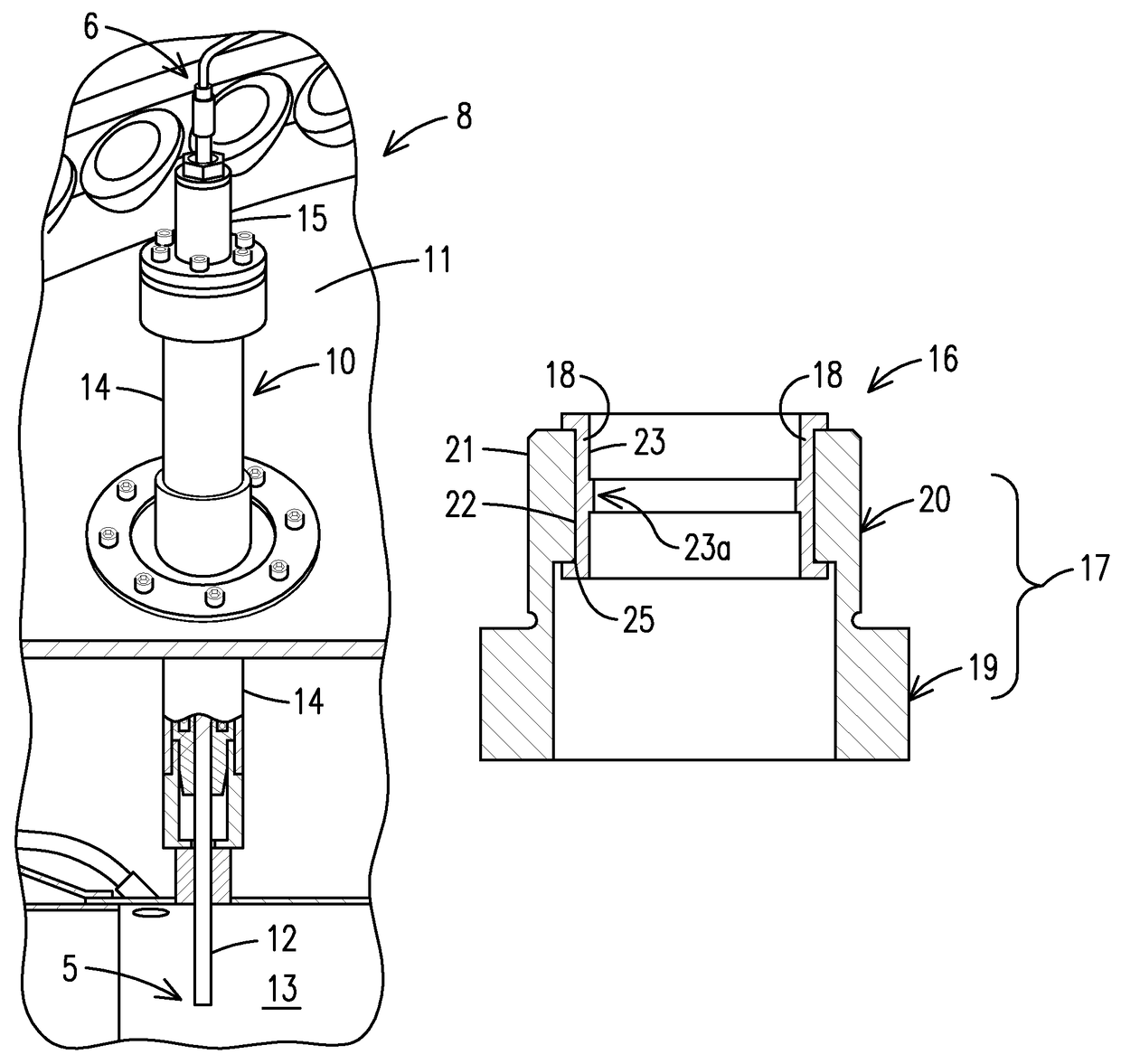
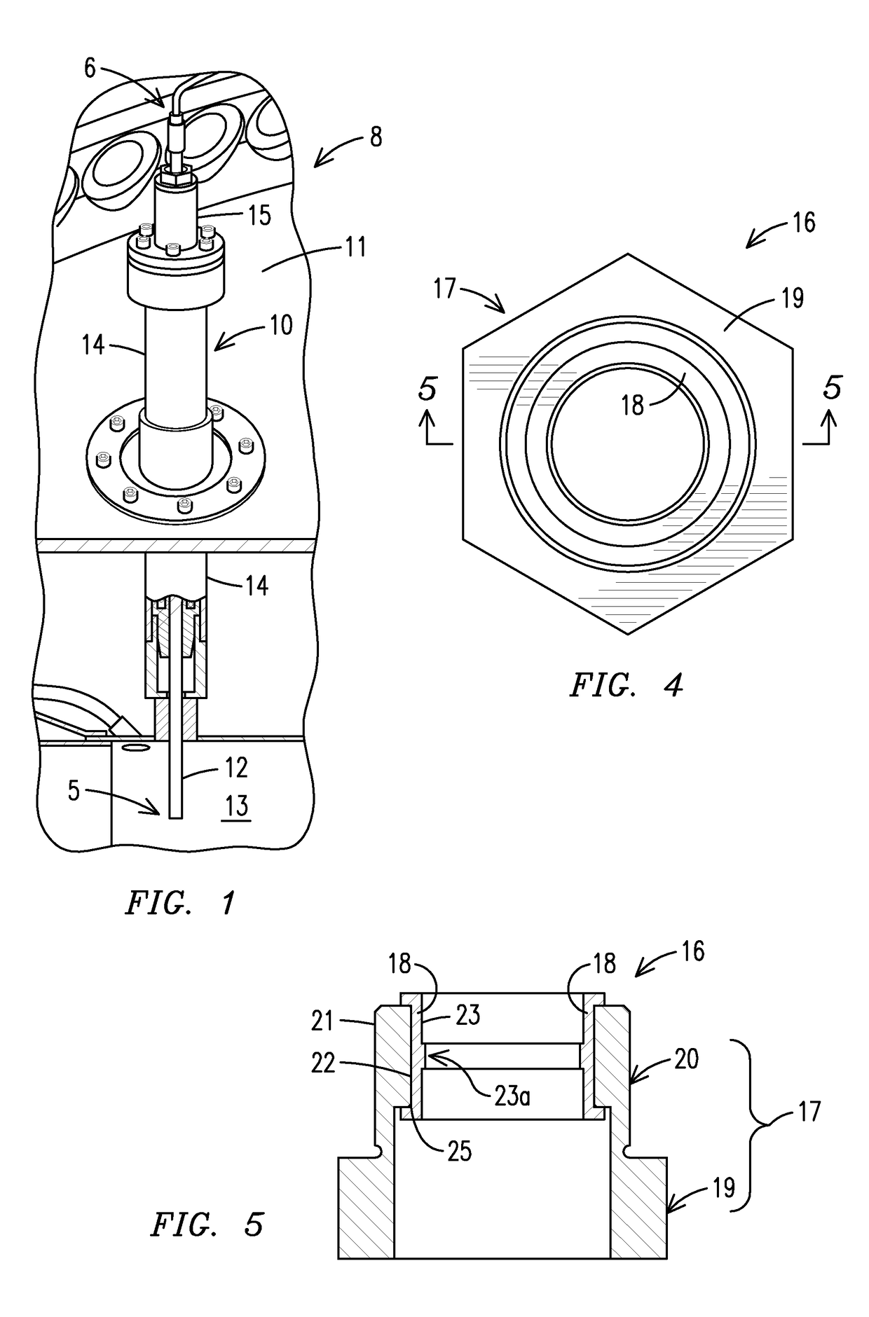
[0025]FIGS. 4 and 5 respectively illustrate a top view and a cross-sectional view of an attachment structure, embodied as a bushing-bearing assembly 16, which may be retrofitted to the cap of an igniter of the type illustrated above. Referring jointly to FIGS. 4 and 5, the assembly 16 includes a bushing 17 and a bearing 18. The bushing 17 is formed by a hexagonal stock portion 19 and a cylindrical portion 20. The cylindrical portion 20 is meant to be arranged inside the cold end of the igniter cap 15 and its outer diameter may be sized suitably based on the inner diameter of the igniter cap 15. An outer surface 21 of the cylindrical portion 20 of the bushing 17 is configured to interface with an inner surface 24 of the cap 15 (see FIG. 6-7) in an end portion of the cap 15 proximate to the cold-end region 6 via, a threaded connection. To this end, the outer surface 21 of the cylindrical portion 20 of the bushing 17 is provided with external threading. The bearing 18 may be glued to a...

second embodiment

[0030]an attachment structure 30 is illustrated in FIGS. 8 and 9, which respectively show untraveled and traveled states of the igniter rod 12. The attachment structure 30 is an extension tube 30. The outer diameter of the extension tube 30 is sized such that it is insertable into the cap 15 via a threaded connection. To that end, the outer surface 31 of the extension tube is externally threaded, that engages in a threaded connection with the threaded inner surface 24 of the cap 15. The inner diameter of the extension tube is sized to provide minimal radial clearance with respect to cold-end of the rod 12. The inner surface 32 of the extension tube 30 forms said guide surface for the igniter rod 12 to move against. The length of the extension tube is sized such that it extends axially outward from the cap 15 toward the cold end. In the present example the extension tube 30 offers a guide length L2 of about 5.0″.


PUM

PropertyMeasurementUnit
inner diameteraaaaaaaaaa
velocityaaaaaaaaaa
pressureaaaaaaaaaa

Abstract

A gas turbine igniter includes an igniter rod disposed within a guide tube configured for travel between a hot-end region and a cold-end region and a cap connected to the guide tube, the cap defining an access passageway for the igniter rod. An attachment structure is provided for reducing the moment loading at the cold end of the igniter rod. The attachment structure has threaded outer surface configured to engage in a threaded connection with a threaded inner surface of the cap in an end portion of the cap that is proximate to the cold-end region, whereby the attachment structure is attachable to the end portion of the cap via the threaded connection. An inner surface of the attachment structure forms a guide surface for the igniter rod, at a reduced radial clearance with the igniter rod in comparison to the cap, proximate to the cold-end region.

Description

FIELD OF INVENTION[0001]Embodiments illustrated herein relate to gas turbine engines, particularly to a gas turbine engine igniter.BACKGROUND OF INVENTION[0002]An igniter for a gas turbine engine should be capable of reliably and cost-effectively igniting a combustible mixture during numerous starts that occur throughout operational cycles of the engine. The igniting function is generally accomplished by electrically-generating a spark across a gap formed between oppositely charged electrodes in a retractable igniter rod. The igniter rod may be a slender columnar structure, which in an ignition-position is deployed into a path of the combustible mixture (e.g., hot gas path) in a combustion chamber. The ignition takes place when velocity and pressure of compressed air in the chamber reach predetermined values.[0003]After ignition, the igniter rod is designed to retract (e.g., to a retracted-position) into a protective structure (e.g., a guide tube) away from the hot combustion enviro...

Claims


Application Information

Patent Timeline
Patent Type & Authority Patents(United States)
IPC IPC(8): F02C7/266
CPCF02C7/266F05D2260/941F05D2260/99Y10T29/49716
Inventor BIRD, DEREK A.
Owner SIEMENS ENERGY INC
Why Eureka
Try Eureka