Permanent magnet rotor

a permanent magnet rotor and permanent magnet technology, applied in the direction of magnetic circuit rotating parts, dynamo-electric machines, magnetic circuit shape/form/construction, etc., can solve the problems of harmful to the operation of the motor, inaccurate and inefficient control, etc., to reduce electromagnetic noise and vibration of the running motor, and improve the effect of working efficiency

Active Publication Date: 2017-08-22
ZHONGSHAN BROAD OCEAN MOTOR MFG
View PDF11 Cites 0 Cited by
  • Summary
  • Abstract
  • Description
  • Claims
  • Application Information

AI Technical Summary

Benefits of technology

[0009]In view of the above-described problems, it is one objective of the invention to provide a permanent magnet rotor that can produce uniformly distributed magnetic field and weaken electromagnetic noise and vibration when the motor is working. In addition, the permanent magnet rotor can speed up the placement of the permanent magnets accurately, and prevent the misplacement thereof, thereby improving the working efficiency.
[0019]Advantages according to embodiments of the invention are summarized as follows: 1) The permanent magnets comprises a first permanent magnet and a second permanent magnet. The first permanent magnet comprises a north pole strong magnetic surface and a south pole weak magnetic surface. The second permanent magnet comprises a north pole weak magnetic surface and a south pole strong magnetic surface. The first permanent magnet and the second permanent magnet are alternately disposed in the radial recesses. The north pole strong magnetic surface of the first permanent magnet and the north pole weak magnetic surface of the second permanent magnet from two adjacent radial recesses are separately attached to two sides of a same magnetic induction block to form a north magnetic pole; and the south pole weak magnetic surface of the first permanent magnet and the south pole strong magnetic surface of the second permanent magnet from two adjacent radial recesses are separately attached to two sides of another same magnetic induction block to form a south magnetic pole. Thus, the magnetic strengths of the magnetic poles are basically equivalent, the magnetic distribution is uniform, thereby weakening electromagnetic noise and vibration of the running motor. 2) The first permanent magnet comprises a first short side on the top thereof, and a first marker is disposed on the first short side; the second permanent magnet comprises a second short side on the top thereof, and a second marker is disposed on the second short side, so that the permanent magnets can be disposed accurately and rapidly, the misplacement thereof is prevented, thereby improving the working efficiency.

Problems solved by technology

However, the assembled rotor produces violent fluctuation and vibration, thereby producing irregular back electromotive force waveform, and resulting in inaccurate and inefficient control.
The magnetic fields formed in FIGS. 3 and 4 are nonuniform, which is harmful to the operation of the motor.
Specifically, the motor produces huge electromagnetic noise and vibration, thereby indirectly causing inaccurate and inefficient control.

Method used


Image

  • Permanent magnet rotor
  • Permanent magnet rotor
  • Permanent magnet rotor

Examples


example 1

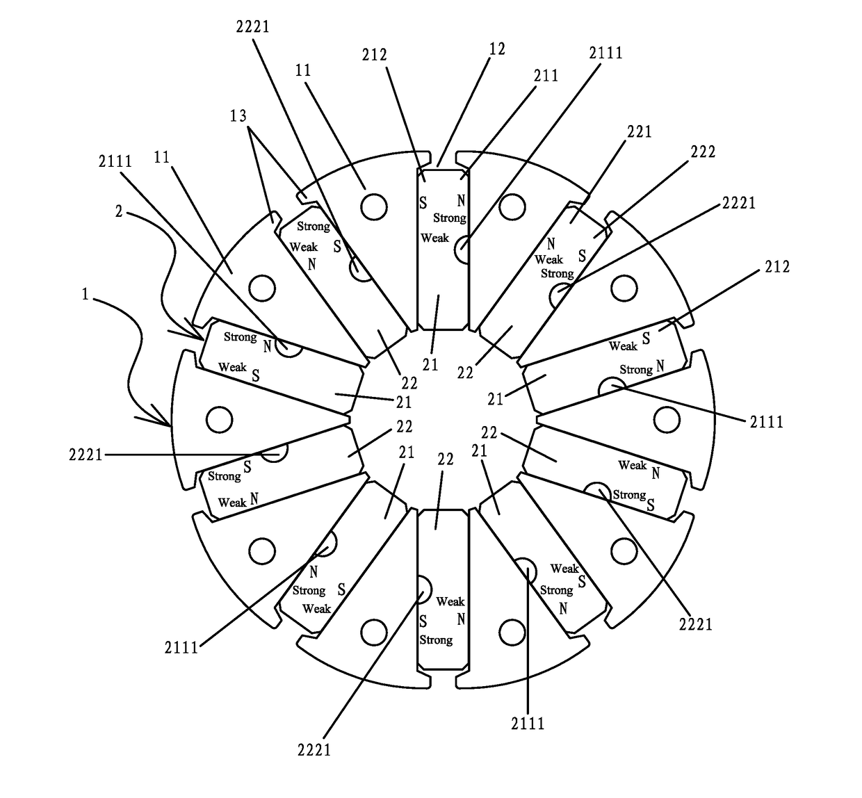
[0034]As shown in FIGS. 5-10, a permanent magnet rotor comprises a rotor core 1 and permanent magnets 2. The rotor core comprises a plurality of magnetic induction blocks 11, and a plurality of radial recesses 12 are formed between every two adjacent magnetic induction blocks for mounting the permanent magnets 2. The magnetic induction blocks 11 at both sides of an opening of the radial recesses protrude to form hook blocks 13. The permanent magnets 2 comprise a first permanent magnet 21 and a second permanent magnet 22. The first permanent magnet 21 comprises a north pole strong magnetic surface 211 and a south pole weak magnetic surface 212. The second permanent magnet 22 comprises a north pole weak magnetic surface 221 and a south pole strong magnetic surface 222. The first permanent magnet 21 and the second permanent magnet 22 are alternately disposed in the radial recesses 122. The north pole strong magnetic surface 211 of the first permanent magnet 21 and the north pole weak m...

example 2

[0035]The permanent magnet rotor disclosed in this example is basically the same as that in Example 1 except that the first short side 2110 is disposed on the south pole weak magnetic surface 212; and the second short side 2220 is disposed on the north pole weak magnetic surface 221, as shown in FIGS. 11-12.

[0036]Principle of the permanent magnet rotor is summarized as follows. The permanent magnets 2 comprise a first permanent magnet 21 and a second permanent magnet 22. The first permanent magnet 21 comprises a north pole strong magnetic surface 211 and a south pole weak magnetic surface 212. The second permanent magnet 22 comprises a north pole weak magnetic surface 221 and a south pole strong magnetic surface 222. The first permanent magnet 21 and the second permanent magnet 22 are alternately disposed in the radial recesses 122. The north pole strong magnetic surface 211 of the first permanent magnet 21 and the north pole weak magnetic surface 221 of the second permanent magnet ...


PUM


Abstract

A permanent magnet rotor including a rotor core and permanent magnets. The rotor core includes a plurality of magnetic induction blocks. A plurality of radial recesses are formed between every two adjacent magnetic induction blocks for mounting the permanent magnets. The magnetic induction blocks protrude at both sides of the opening of the radial recesses to form hook blocks. The permanent magnets include a first permanent magnet and a second permanent magnet. The first permanent magnet includes a north pole strong magnetic surface and a south pole weak magnetic surface. The second permanent magnet includes a north pole weak magnetic surface and a south pole strong magnetic surface. The first permanent magnet and the second permanent magnet are alternately disposed in the radial recesses.

Description

CROSS-REFERENCE TO RELATED APPLICATIONS[0001]This application is a continuation-in-part of International Patent Application No. PCT / CN2014 / 072702 with an international filing date of Feb. 28, 2014, designating the United States, and further claims priority benefits to Chinese Patent Application No. 201320539733.3 filed Aug. 30, 2013. The contents of all of the aforementioned applications, including any intervening amendments thereto, are incorporated herein by reference. Inquiries from the public to applicants or assignees concerning this document or the related applications should be directed to: Matthias Scholl P. C., Attn.: Dr. Matthias Scholl Esq., 245 First Street, 18th Floor, Cambridge, Mass. 02142.BACKGROUND OF THE INVENTION[0002]Field of the Invention[0003]The invention relates to a permanent magnet rotor.[0004]Description of the Related Art[0005]As shown in FIG. 1, a typical permanent magnet rotor includes a rotor core A1 and permanent magnets A2. The rotor core A1 includes...

Claims


Application Information

Patent Timeline
Patent Type & Authority Patents(United States)
IPC IPC(8): H02K1/27
CPCH02K1/2773
Inventor PAN, MINGPAN
Owner ZHONGSHAN BROAD OCEAN MOTOR MFG
Why Eureka
Try Eureka