Liquid ejection head, recording apparatus and heat radiation method for liquid ejection head

a liquid ejection head and recording apparatus technology, applied in printing, inking apparatus, other printing apparatus, etc., can solve the problems of large variation in the amount of liquid ejected, and achieve the effect of suppressing heat conduction between the recording element substrates

Active Publication Date: 2017-08-29
CANON KK
View PDF19 Cites 8 Cited by
  • Summary
  • Abstract
  • Description
  • Claims
  • Application Information

AI Technical Summary

Benefits of technology

[0009]In the present invention, because the first thermal resistance is higher than the second thermal resistance, the heat that is generated in each recording element substrate (each energy generating element) along with the liquid ejection and is transferred to the first support member is more transferred to the second support member located immediately therebelow than to the other recording element substrates. Hence, the heat conduction between the recording element substrates can be suppressed.

Problems solved by technology

As a result, it is concerned that variations in the amount of ejected liquid are large, and may have influences on image quality.

Method used


Image

  • Liquid ejection head, recording apparatus and heat radiation method for liquid ejection head
  • Liquid ejection head, recording apparatus and heat radiation method for liquid ejection head
  • Liquid ejection head, recording apparatus and heat radiation method for liquid ejection head

Examples


first embodiment

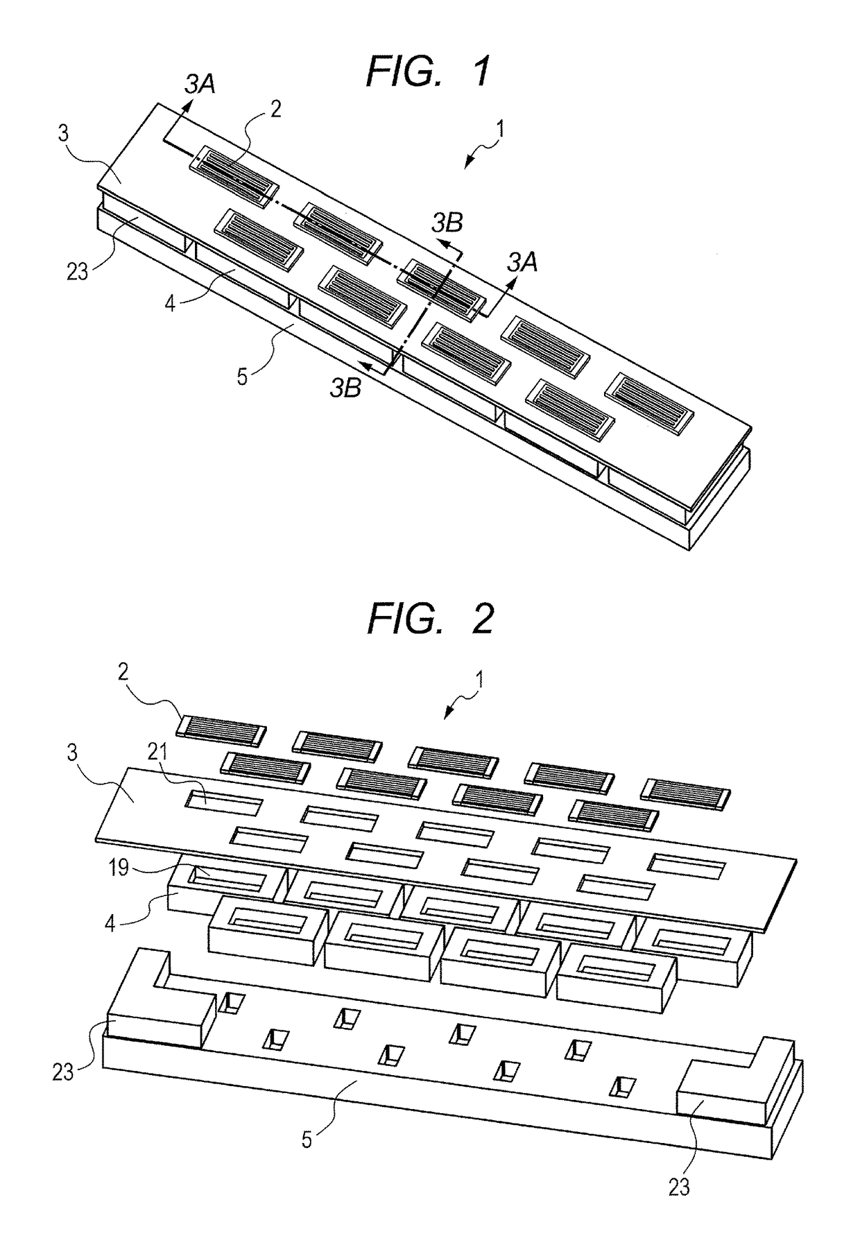
[0037]A first embodiment of the present invention is described. FIG. 1 is a perspective view of a liquid ejection head of the first embodiment. FIG. 2 is an exploded perspective view of the liquid ejection head illustrated in FIG. 1. A liquid ejection head 1 of the present embodiment illustrated in FIG. 1 and FIG. 2 includes a plurality of recording element substrates 2, a first support member 3 that supports the plurality of recording element substrates 2, a plurality of second support members 4 that supports the first support member 3, and a base substrate 5 that supports the plurality of second support members 4.

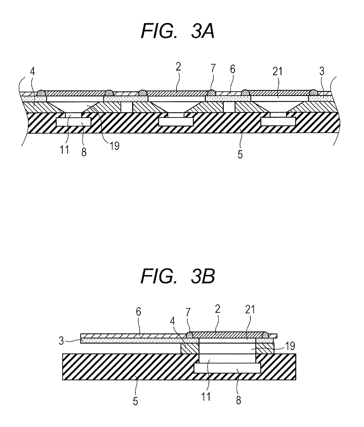
[0038]FIG. 3A is a cross-sectional view taken along a sectional line 3A-3A illustrated in FIG. 1. FIG. 3B is a cross-sectional view taken along a sectional line 3B-3B illustrated in FIG. 1. Flexible printed circuits (hereinafter, referred to as FPC) 6 and sealants 7 illustrated in FIGS. 3A and 3B are omitted in FIGS. 1 and 2.

[0039]The plurality of recording element substr...

second embodiment

[0062]A second embodiment of the present invention is described. Hereinafter, differences from the first embodiment are mainly described. FIG. 11 is a block diagram illustrating a configuration of a main part of a liquid ejection head of the second embodiment. The liquid ejection head of the present embodiment includes: a temperature sensor 33 that detects the temperature of each recording element substrate 2; and a heating member 34 that heats the recording element substrate 2. A control unit 35 is provided to a recording apparatus main body electrically connected to the recording element substrates 2, and the control unit 35 controls an operation of the heating member 34 based on an output value from the temperature sensor 33. In the present embodiment, the temperature sensor 33 and the heating member 34 are provided to the substrate 18 (see FIG. 4B) of each recording element substrate 2. The temperature sensor 33 and the heating member 34 are provided between the liquid supply po...

third embodiment

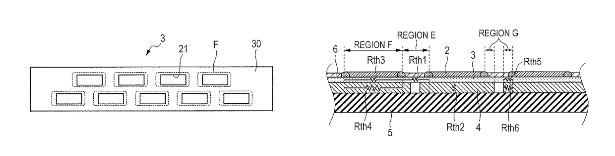
[0066]A third embodiment of the present invention is described. Hereinafter, differences from the first embodiment are mainly described. FIG. 13A is a top view of a first support member 3c provided to a liquid ejection head of the third embodiment. FIG. 13A is a top view illustrating the entirety of the first support member 3c of the third embodiment. FIG. 13B is an enlarged view of a portion around a through-hole 21 in the first support member 3c illustrated in FIG. 13A.

[0067]As illustrated in FIG. 13A, the first support member 3c of the present embodiment includes beam parts 36 that extend across each through-hole 21. In the present embodiment, three beam parts 36 are provided, but the number of the beam parts 36 is not particularly limited.

[0068]The beam parts 36 are members for reducing a temperature difference inside of each recording element substrate 2 caused along with the liquid ejection. For example, in a ejection mode in which only a particular ejection orifice line 12 of...


PUM


Abstract

Provided is a liquid ejection head including: a plurality of recording element substrates including energy generating elements that generate ejection energy for ejecting liquid from ejection orifices; a first support member that supports the plurality of recording element substrates such that the recording element substrates are arranged in one or more lines on a main surface of the first support member; and a second support member that supports the first support member on a surface opposite to the main surface. A first thermal resistance concerning an in-plane direction parallel to the main surface, of a region between the recording element substrates in the first support member is higher than a second thermal resistance concerning a thickness direction of the second support member, of a projection region that overlaps with each recording element substrate in the second support member.

Description

BACKGROUND OF THE INVENTION[0001]Field of the Invention[0002]The present invention relates to a liquid ejection head that ejects liquid, a recording apparatus including the liquid ejection head and a heat radiation method for the liquid ejection head.[0003]Description of the Related Art[0004]A so-called thermal method is known as a liquid ejection method for a liquid ejection head. In the thermal method, liquid is heated to be boiled, and the force of bubbles generated by the boiling is used to eject the liquid from ejection orifices. In recent years, in order to meet a demand for high-speed image recording, achievement of a thermal liquid ejection head having a large recording width is desired. An example of such a liquid ejection head is disclosed in Japanese Patent No. 4999663.[0005]The liquid ejection head disclosed in Japanese Patent No. 4999663 includes: a plurality of recording element substrates including ejection orifice lines in which a plurality of ejection orifices is li...

Claims


Application Information

Patent Timeline
Patent Type & Authority Patents(United States)
IPC IPC(8): B41J29/377B41J2/14B41J2/045B41J2/155
CPCB41J2/04528B41J2/0458B41J2/04563B41J2/04581B41J2/1408B41J2/155B41J2202/12B41J2202/20
Inventor YAMADA, KAZUHIROMORIGUCHI, TAKUTOTAMENAGA, ZENTAROIWANAGA, SHUZOMORIYA, TAKATSUGU
Owner CANON KK
Why Eureka
Try Eureka