Hoop spring in a pressure reactive piston

a technology of reactive pistons and springs, applied in the field of springs, can solve the problems of uneven stress distribution of belleville springs, inability to deflect belleville springs as desired, and inability to meet the desired application in the prp, so as to achieve the effect of reducing the pressure of the peak cylinder, reducing the compression ratio, and increasing the compression ratio

Active Publication Date: 2017-08-29
FORD GLOBAL TECH LLC
View PDF23 Cites 1 Cited by
  • Summary
  • Abstract
  • Description
  • Claims
  • Application Information

AI Technical Summary

Benefits of technology

[0002]A pressure reactive piston (PRP) situated in a cylinder of an engine may comprise a two-piece piston, wherein the two-piece piston includes a piston crown and a piston trunk. By integrating a separately actuated piston crown with a piston trunk, peak cylinder pressures may be reduced at higher loads without an additional control device. As such, the engine may operate at a higher compression ratio during lower load conditions, and may operate at a lower compression ratio during higher load conditions. Thus, peak temperatures and pressures within the combustion chamber may be reduced.
[0007]In this way, a hoop spring housed within a two-piece pressure reactive piston may provide variable compression ratio to the engine. By forming the spring of three distinct lightweight elements, a mass of the hoop spring may be reduced. The reduced mass of the hoop spring can lower the weight of the two-piece pressure reactive piston, improving engine performance. Moreover, the hoop spring may experience more uniform stress distribution, thereby increasing durability. Overall, engine efficiency may be improved while enhancing fuel economy.

Problems solved by technology

Further, the Belleville springs may have an uneven stress distribution.
Further still, Belleville springs may not deflect as desired during certain loads.
Specifically, spring rates of Belleville springs may not be suitable for the desired application in a PRP.
As a result, there may be an increased risk of knock and reduction in engine efficiency and fuel economy.

Method used


Image

  • Hoop spring in a pressure reactive piston
  • Hoop spring in a pressure reactive piston
  • Hoop spring in a pressure reactive piston

Examples


Embodiment Construction

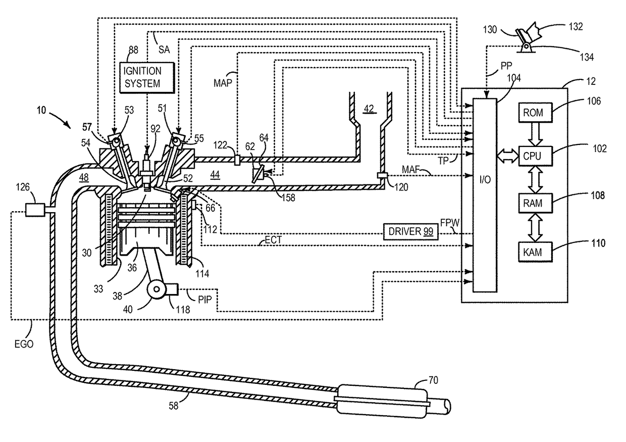
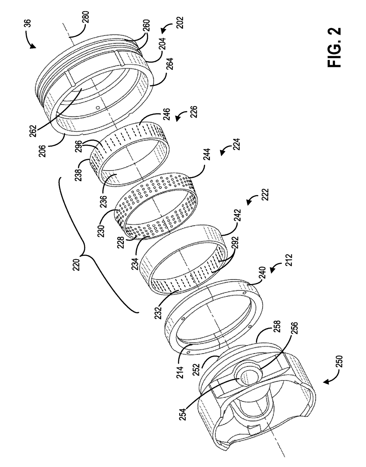
[0017]The following description relates to systems and methods for varying a compression ratio of an engine, such as the example engine depicted in FIG. 1. The compression ratio may be adjusted via including a spring assembly, or a hoop spring, within a two-piece piston, the two-piece piston having a trunk portion and a crown portion, as shown in FIG. 2. In particular, the hoop spring may include a first ring, a second ring, and a third ring, wherein the second ring may include a pluraltiy of rolling elements (FIG. 3). As such, the hoop spring may assembled together as shown in FIG. 4, and mounted on the trunk portion of the piston. Features of the hoop spring may be varied depending on desired spring rate and preload characteristics (FIGS. 5A-5D). In one embodiment, the hoop spring, may control the compression ratio by moving between a first state, or compressed position (FIG. 6A), and a second state, or expanded position (FIG. 6B). Further, spark timing may be adjusted based on th...


PUM


Abstract

Systems and methods are provided for varying a compression ratio in an engine having a pressure reactive piston. The pressure reactive piston may include a piston crown, and a spring positioned within the piston crown, wherein the spring includes a first ring, a second ring comprising a plurality of apertures, a rolling element positioned within each of the plurality of apertures, and a third ring. The first ring, the second ring, and the third ring of the spring may be arranged concentrically and the second ring may be positioned between the first ring and the third ring.

Description

FIELD[0001]The present disclosure relates to a spring positioned in a piston within an internal combustion engine.BACKGROUND AND SUMMARY[0002]A pressure reactive piston (PRP) situated in a cylinder of an engine may comprise a two-piece piston, wherein the two-piece piston includes a piston crown and a piston trunk. By integrating a separately actuated piston crown with a piston trunk, peak cylinder pressures may be reduced at higher loads without an additional control device. As such, the engine may operate at a higher compression ratio during lower load conditions, and may operate at a lower compression ratio during higher load conditions. Thus, peak temperatures and pressures within the combustion chamber may be reduced.[0003]An example pressure reactive piston assembly is described by Brevick et al. in U.S. Pat. No. 5,755,192. Herein, the pressure reactive piston assembly includes a trunk portion, a crown portion slidably mounted upon the trunk portion, and a resilient element. T...

Claims


Application Information

Patent Timeline
Patent Type & Authority Patents(United States)
IPC IPC(8): F02B75/04F02P5/15F02D15/04F02D13/02
CPCF02B75/044F02D13/0207F02D15/04F02P5/151F02P5/145F02P5/152Y02T10/12Y02T10/40
Inventor BREVICK, JOHN EDWARD
Owner FORD GLOBAL TECH LLC
Why Eureka
Try Eureka