Beam clamp

a beam clamp and beam technology, applied in the field of beam clamps, to achieve the effect of accurate laser drilling, high fastening performance, and high processing precision and efficiency

Active Publication Date: 2017-08-29
JIANGMEN EUROFIX METAL & RUBBER PROD
View PDF29 Cites 7 Cited by
  • Summary
  • Abstract
  • Description
  • Claims
  • Application Information

AI Technical Summary

Benefits of technology

[0010]The present invention has the advantages that: according to the product, the plate material is bent and butt-jointed to form the beam clamp body, and holes are accurately laser bored; therefore, the processing precision and efficiency are very high; moreover, three-point clamping is applied on the clamping jaws and the bolt, thus having a very high fastening performance; meanwhile, the entire structure strength is high, the load performance is good, the size is small, and the beam clamp has a good adaptability.

Problems solved by technology

However, this clamp requires that the edges at the two sides of the beam shall be provided with edge for clamping, for example, an “I” beam, and cannot be applied to a beam only having a single-side protruded edge.

Method used


Image

  • Beam clamp
  • Beam clamp
  • Beam clamp

Examples


Embodiment Construction

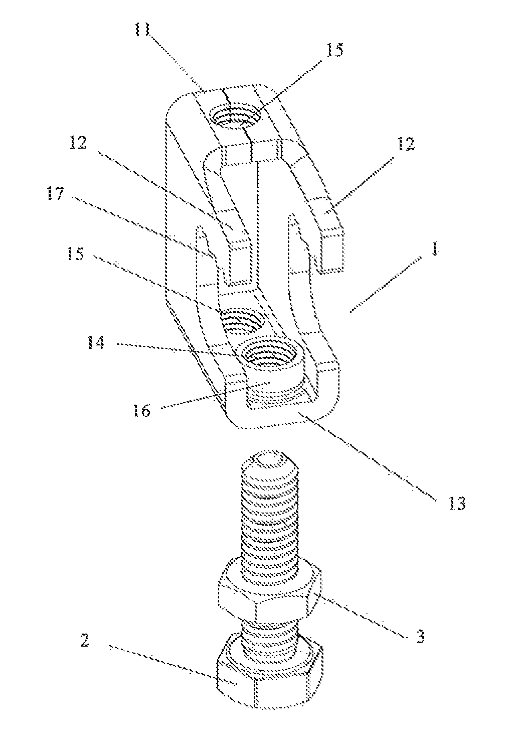
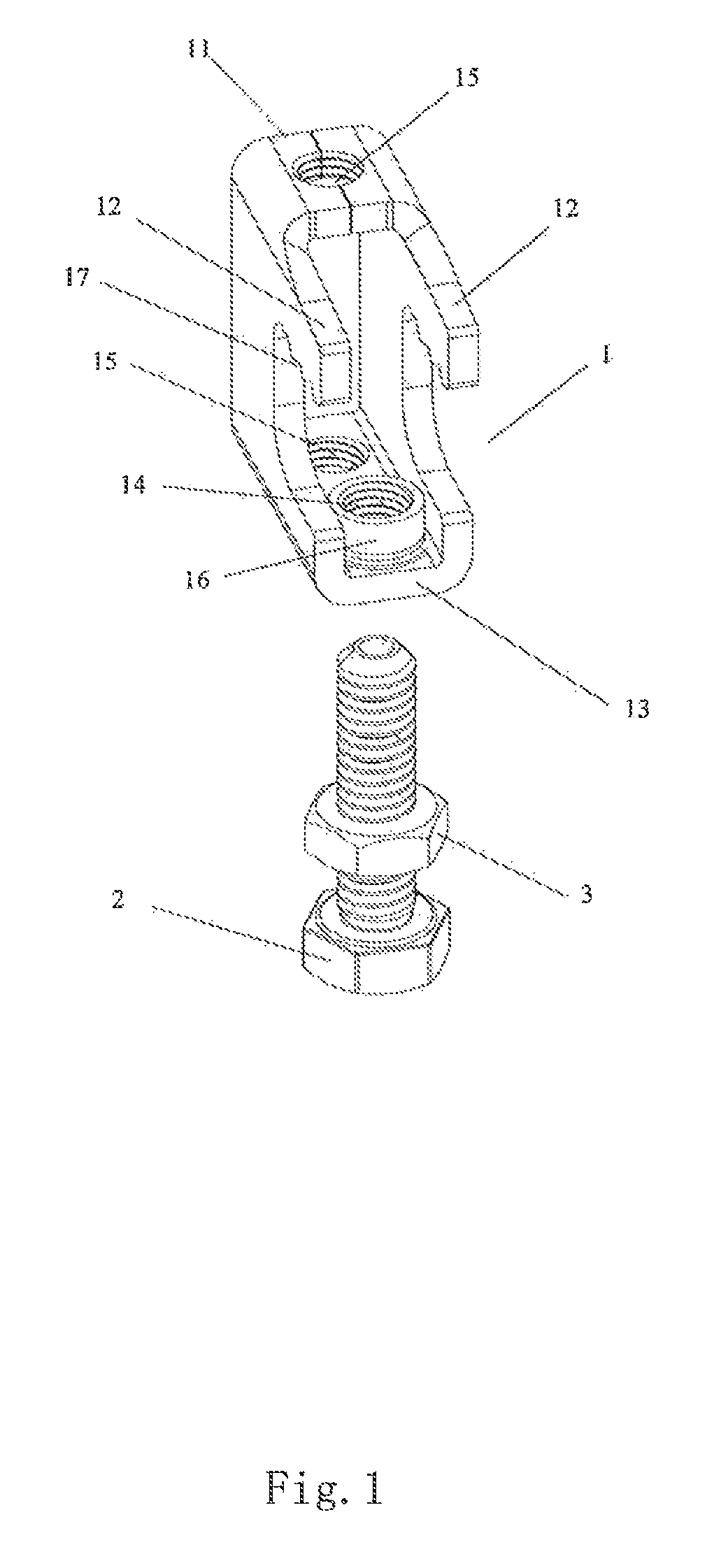
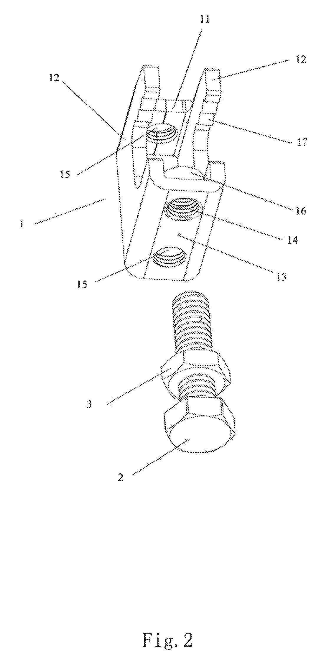
[0014]Referring to FIG. 1 and FIG. 2, a beam clamp includes a clamp body 1, wherein the clamp body 1 is a rectangular tube body shape symmetrically bent and butt-jointed by a plate material. One side of the clamp body 1 housing a butt seam is a butt-joint face 11, the butt seam is located in the middle of the butt-joint face 11, and symmetrical clamping jaws 12 are protruded on the two sides of the clamp body 1 at the two sides of the butt-joint face 11. A clamping plate face 13 is convexly disposed on one side of the clamp body 1 opposite to the butt-joint face 11, the clamping jaws 12 and the clamping plate face 13 form an arched clamping opening, for adapting to enclose the edge of the beam. A screw hole 14 corresponding to the clamping jaw 12 is laser bored on the clamping plate face 13, the processing efficiency of the laser boring is very high and the precision thereof is also very high, The screw hole 14 is correspondingly between the two clamping jaws 12, and then the screw ...


PUM


Abstract

A beam clamp, including a clamp body having a rectangular shape symmetrically bent and butt-jointed by a plate material is described. On one side of the body housing a butt seam is a butt-joint face, and clamping jaws are protruded on the two sides of the body at the two sides of the butt-joint face. A clamping plate face is convexly disposed on one side of the body opposite the butt-joint face, and a screw hole corresponding to the clamping jaw is bored on the plate face. The screw hole is tapped and a bolt is disposed therein. The bolt and jaws form three-point clamping, providing high fastening performance. Corresponding threaded rod holes are bored on the plate face and butt-joint face and tapped. The resulting clamp has high processing precision, efficiency, and adaptability; the structure strength is high; load performance is good; and the size is small.

Description

FIELD OF THE INVENTION[0001]The present invention relates to a clamp, and in particular, to a beam clamp.BACKGROUND OF THE INVENTION[0002]A beam clamp refers to a clamp that is clamped, such as, on a beam in a workshop. The existing beam clamp usually adopts two claws to clamp edges at the two sides of a beam body, and uses bolts to fasten the claw positions, thus fixing the beam clamp on the beam, and then being capable of realizing other support and fixation effects through the clamp. However, this clamp requires that the edges at the two sides of the beam shall be provided with edge for clamping, for example, an “I” beam, and cannot be applied to a beam only having a single-side protruded edge. Therefore, it needs a better beam clamp structure which not only can realize single-side clamping and fixation, but also can ensure to provide enough support strength, and can bear weight during long-term high-load application.SUMMARY OF THE INVENTION[0003]In order to overcome the defects ...

Claims


Application Information

Patent Timeline
Patent Type & Authority Patents(United States)
IPC IPC(8): F16L3/24F16B2/06
CPCF16B2/065
Inventor JIANG, SHIZHONG
Owner JIANGMEN EUROFIX METAL & RUBBER PROD
Why Eureka
Try Eureka