
Machine for processing optical workpieces, in particular plastic spectacle lenses

a technology for processing machines and workpieces, applied in the direction of lenses, manufacturing tools, spectacles/goggles, etc., can solve the problems of undesired axial displacement and vibration, and achieve the effects of compact construction, high level of rigidity, and low weigh

Active Publication Date: 2017-09-05
SATISLOH AG
View PDF24 Cites 0 Cited by
  • Summary
  • Abstract
  • Description
  • Claims
  • Application Information

AI Technical Summary

Benefits of technology

The patent is about a way to keep a machine's cutter in the correct position even when it gets hot. This means that tool holders can be used, which can be preset outside the machine to save time. The machine's housing is designed to transfer force and heat in a symmetrical way, and is compact.

Problems solved by technology

However, these types of cubic machine beds can be subjected to not insubstantial structural deformations under highly dynamic loads, for example due to bending and torsion of the machine bed.
These deformations can then be transmitted to the tool and workpiece drives arranged above the cubic machine bed structure, so that there is a risk there of undesired axial displacements and vibrations, which can have the consequence of chatter marks or the like and ultimately inaccuracies in the workpieces being processed.

Method used


Image

  • Machine for processing optical workpieces, in particular plastic spectacle lenses
  • Machine for processing optical workpieces, in particular plastic spectacle lenses
  • Machine for processing optical workpieces, in particular plastic spectacle lenses

Examples


Embodiment Construction

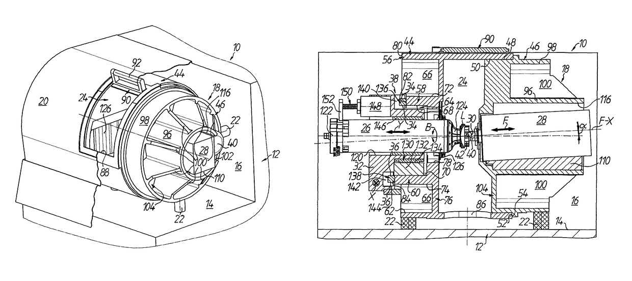
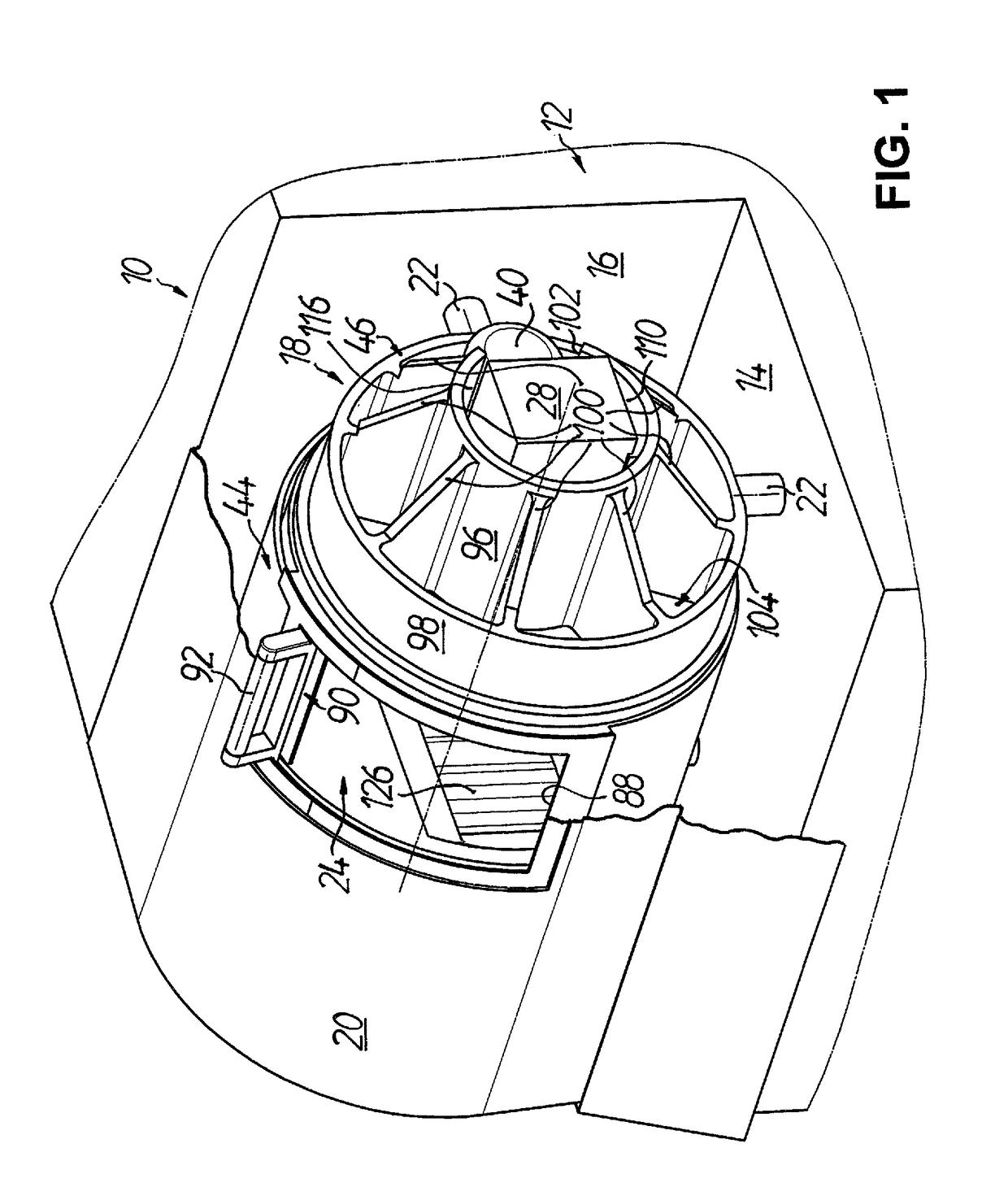
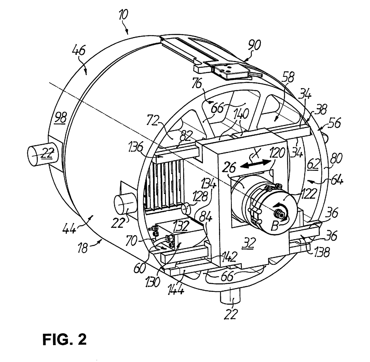
[0038]A CNC-controlled machine, particularly for end-face surface-processing of spectacle lenses L of plastics material, is denoted by 10 in FIGS. 1 to 8. The machine 10 comprises a machine frame 12, which is illustrated only schematically and in broken-away form in FIGS. 1, 3 to 6 and 8 and which can be constructed as a welded construction of metal sheets, with a horizontally extending upper side 14 and a vertically extending rear wall 16, which downwardly and rearwardly bound a receiving space, which is substantially L-shaped as seen in cross-section, for a machine housing 18 described in more detail in the following. To the front, top and sides the receiving space for the machine housing 18 is bounded by a partly transparent casing 20 which is removable from the machine frame 12 and which is similarly illustrated only schematically and in broken-away form in FIG. 1. A machine control, a control unit, supply devices for current, compressed air and coolant as well as a device for c...


PUM

PropertyMeasurementUnit
intrinsic weightaaaaaaaaaa
heightaaaaaaaaaa
optical effectaaaaaaaaaa

Abstract

The invention relates to a machine for processing plastic workpieces. A machine housing surrounds a working chamber located between a workpiece spindle for rotationally driving the workpieces about a workpiece axis of rotation and a fast tool servo for producing an oscillating feeding movement of a rotary tool in the direction of the workpieces. The workpiece spindle is provided with a carriage which can be driven and is guided on at least two guide surfaces of a guiding arrangement in order to produce a relative advancing movement between the workpiece and the rotary tool. The advancing movement runs transversely with respect to the feeding movement and defining therewith a processing plane in which during processing the rotary tool engages with the workpiece. The guiding arrangement is mounted on the machine housing such that the processing plane extends between the two guide surfaces.

Description

TECHNICAL FIELD[0001]The present invention relates generally to a machine for processing optical workpieces. In particular, the invention relates to a machine for processing spectacle lenses of plastics material such as is widely used in so-called “RX workshops”, i.e. production facilities for large-scale production of individual spectacle lenses according to prescription.PRIOR ART[0002]For the processing of plastics material spectacle lenses there is usually a spectacle lens blank, also termed “blank”, which is injection-molded from plastics material (for example polycarbonate, CR 39, HI index, etc.) and which has a standardized finished convex outer surface with, for example, a spherical or progressive shape. The usually concave inner or prescription surfaces receive, by way of a cutting machining, a spherical, aspherical, toroidal, atoroidal, progressive or free-shape geometry (progressive surfaces) depending on the respectively desired optical effect. The typical conventional se...

Claims


Application Information

Patent Timeline
Patent Type & Authority Patents(United States)
IPC IPC(8): B23B5/00B23B5/36B24B13/04B24B41/02B23C3/00B23B7/02B23B29/04B23Q1/01
CPCB23B5/36B23B7/02B23B29/04B23C3/00B24B13/046B24B41/02B23B2215/40B23C2215/40B23Q1/015Y10T82/2502
Inventor WALLENDORF, STEFFENSCHAFER, HOLGERSAVOIE, MARC
Owner SATISLOH AG
Learn More