Driving circuit, converter and driving method

a driving circuit and converter technology, applied in the direction of pulse technique, process and machine control, instruments, etc., can solve the problem of hard speed up of the turn-on speed of the semiconductor switch element, and achieve the effect of stable driving voltage and faster turn-on speed

Active Publication Date: 2017-09-05
DELTA ELECTRONICS INC
View PDF14 Cites 0 Cited by
  • Summary
  • Abstract
  • Description
  • Claims
  • Application Information

AI Technical Summary

Benefits of technology

[0009]In view of the above, the driving circuit in the aforementioned embodiment outputs a first voltage having a higher voltage before outputting a second voltage having a lower voltage. The first voltage is provided to a switch element such that the switch element has a faster turn-on speed, and the second voltage is provided to the switch element such that the switch element has a stable driving voltage after it is turned on.

Problems solved by technology

Accordingly, the turn-on speed of the semiconductor switch element is hard to speed up.

Method used


Image

  • Driving circuit, converter and driving method
  • Driving circuit, converter and driving method
  • Driving circuit, converter and driving method

Examples


Embodiment Construction

[0021]The present disclosure will now be described more fully hereinafter with reference to the accompanying drawings, in which exemplary embodiments of the disclosure are shown. This disclosure may, however, be embodied in many different forms and should not be construed as limited to the embodiments set forth herein. Rather, these embodiments are provided so that this disclosure will be thorough and complete, and will fully convey the scope of the invention to those skilled in the art. Like reference numerals refer to like elements throughout.

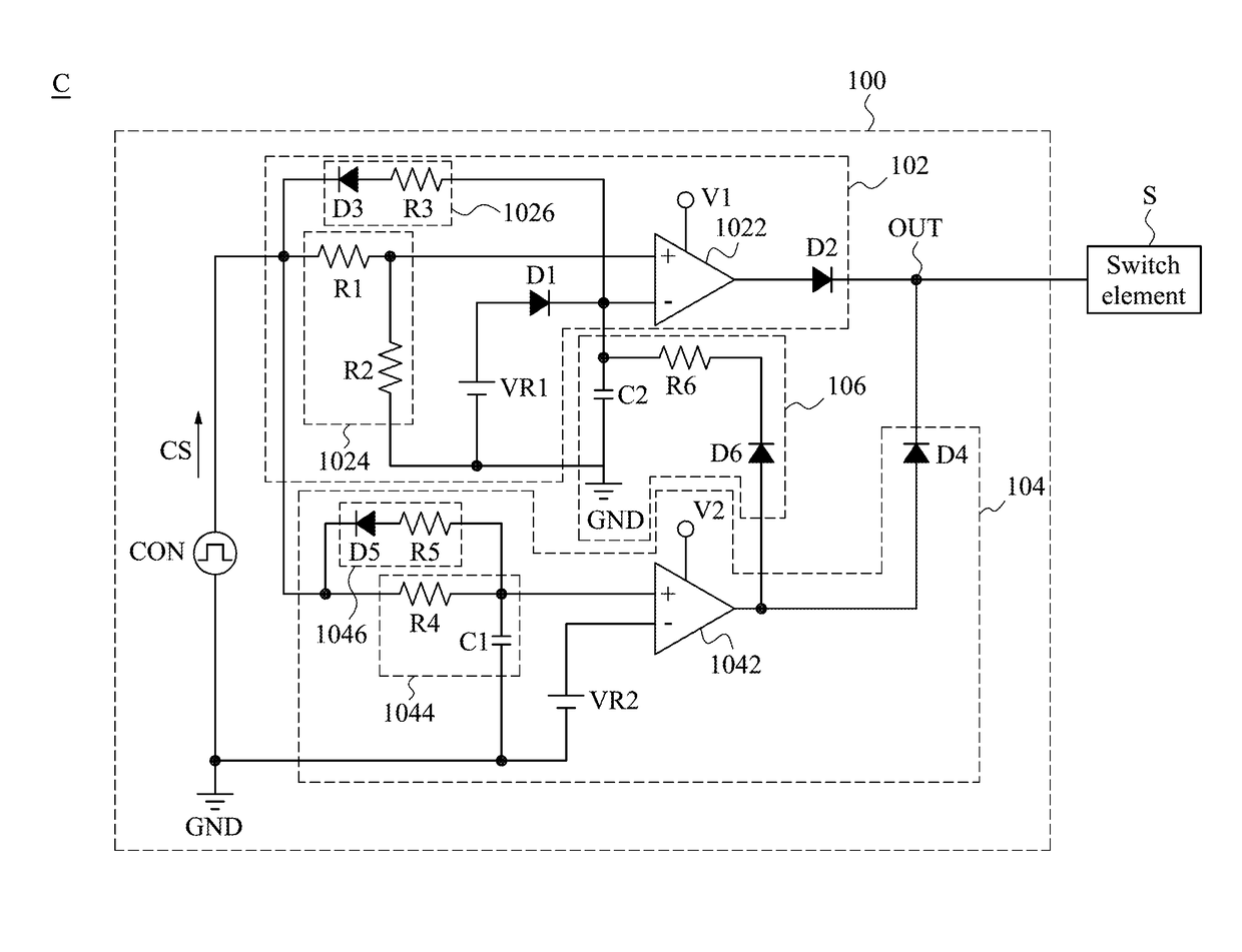
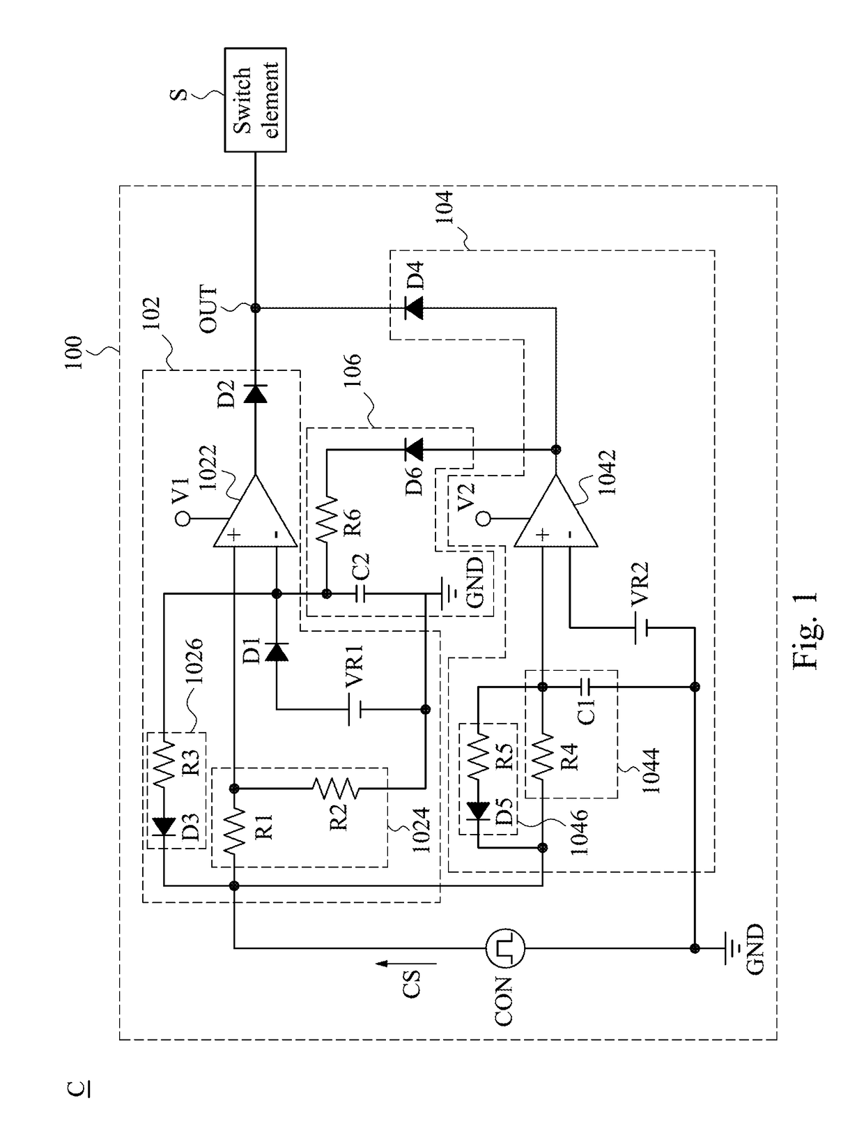
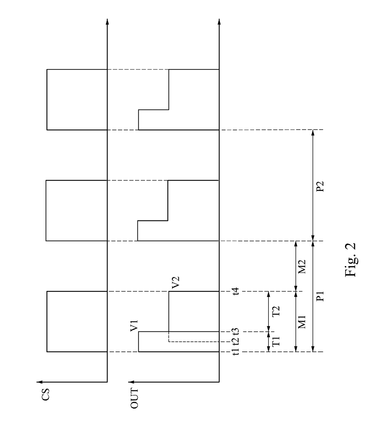
[0022]FIG. 1 is a block diagram illustrating a driving circuit 100 and a switch element S according to one embodiment of the present disclosure. FIG. 2 is a waveform diagram of a control signal CS and a voltage of a main output terminal OUT of the driving circuit 100 of FIG. 1.

[0023]In some embodiments, signals outputted at the main output terminal OUT of the driving circuit 100 are configured to drive the switch element S. As illustrated in ...


PUM


Abstract

A driving circuit includes a main output terminal electrically coupled to a switch element, a first voltage generating circuit and a second voltage generating circuit. The first voltage generating circuit is electrically coupled with the main output terminal. The first voltage generating circuit comprises a first comparator and a voltage divider circuit. The first voltage generating circuit is configured to generate a first voltage at the main output terminal during a predetermined time interval of a turn-on duration of a switching period. The second voltage generating circuit is electrically coupled with the main output terminal. The second voltage generating circuit is configured to generate a second voltage at the main output terminal during a remaining time interval of the turn-on duration of the switching period. The predetermined time interval is ahead of the remaining time interval, and the first voltage is higher than the second voltage.

Description

BACKGROUND[0001]Technical Field[0002]The present disclosure relates to a driving circuit, a converter and a driving method. More particularly, the present disclosure relates to a driving circuit, a converter and a driving method that may speed up driving velocity of a switch element.[0003]Description of Related Art[0004]The current technology is such that a square wave is configured to drive a semiconductor switch element. When the square wave is fixed, a turn-on speed of the semiconductor switch element is fixed. Accordingly, the turn-on speed of the semiconductor switch element is hard to speed up.SUMMARY[0005]The present disclosure provides a driving circuit and a driving method to solve the foregoing problems.[0006]One embodiment of the present disclosure is related to a driving circuit. The driving circuit is for driving a switch element. The driving circuit includes a main output terminal, a first voltage generating circuit and a second voltage generating circuit. The main out...

Claims


Application Information

Patent Timeline
Patent Type & Authority Patents(United States)
IPC IPC(8): G05F1/56H03K17/042G05F5/00H03K5/24H02M3/156
CPCH03K17/04206H02M3/156H03K5/24H02M1/36H03K17/04123H03K17/163H03K17/164
Inventor HU, CHIH-I
Owner DELTA ELECTRONICS INC
Why Eureka
Try Eureka