Transaxle

a transaxle and hst technology, applied in the field of transaxles, can solve the problems of wrongly influencing the activation of the hst and causing noise, and achieve the effect of reducing the number of components and costs

Active Publication Date: 2017-09-12
KANZAKI KOKYUKOKI MFG
View PDF7 Cites 0 Cited by
  • Summary
  • Abstract
  • Description
  • Claims
  • Application Information

AI Technical Summary

Benefits of technology

[0007]An object of the invention is to provide a transaxle including an HST, configured so as to protect the HST from fluid contaminated with air caused by a gear train disposed together with the HST in a casing.
[0011]Therefore, even if the gear train agitates or splashes fluid of the fluid sump in the gear chamber so as to contaminate the fluid with air, the partition hinders the fluid contaminated with air from entering the fluid sump in the HST chamber, thereby reducing air mixed in the fluid sump in the HST chamber so as to keep a proper activation of the HST and so as to reduce noise.
[0013]Therefore, no additional component is needed to serve as the power transmission means, thereby reducing the number of components and costs.
[0015]Therefore, a portion of the casing incorporating the hydraulic motor is minimized vertically, and a horizontal distance between the HST and the gear train is reduced so as to minimize the casing in the direction of alignment of the HST chamber and the gear chamber. Further, the vertically extended partition surely separates the HST chamber and the gear chamber from each other, while allowing the vertically slant extended hydraulic motor to pass through the opening in the partition.
[0017]Therefore, in the condition that the casing includes the divisional housings for facility in assembling and maintenance, the ribs formed on the divisional housings are used to constitute the partition, so that no additional component is needed to serve as the partition, thereby reducing the number of components and costs. Only if the divisional housings are joined to each other to complete the casing, the partition with the opening is completed, thereby facilitating assembling of the partition having the opening in the casing.

Problems solved by technology

In this state, a bottom portion of the gear train is also submerged in the fluid sump so that rotating gears agitate the fluid sump so as to tend to contaminate the fluid sump with air, thereby wrongly influencing activation of the HST and causing noise.

Method used


Image

  • Transaxle
  • Transaxle
  • Transaxle

Examples


Embodiment Construction

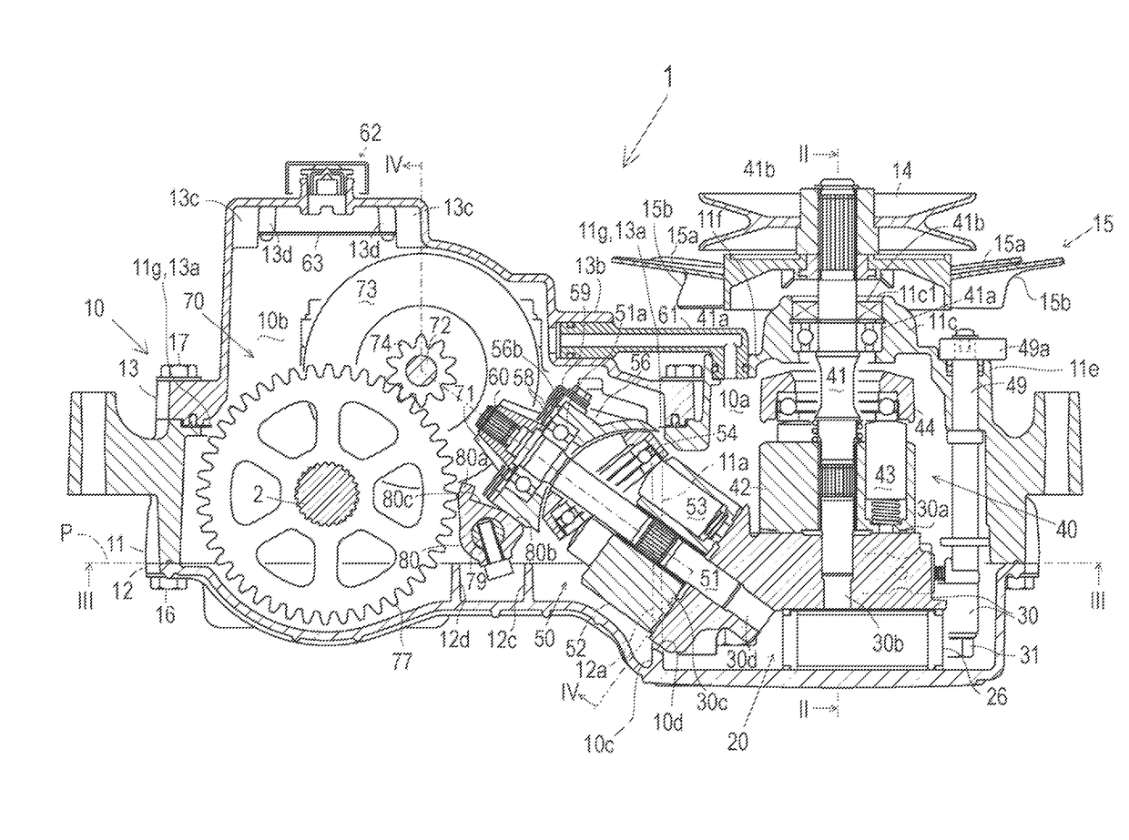
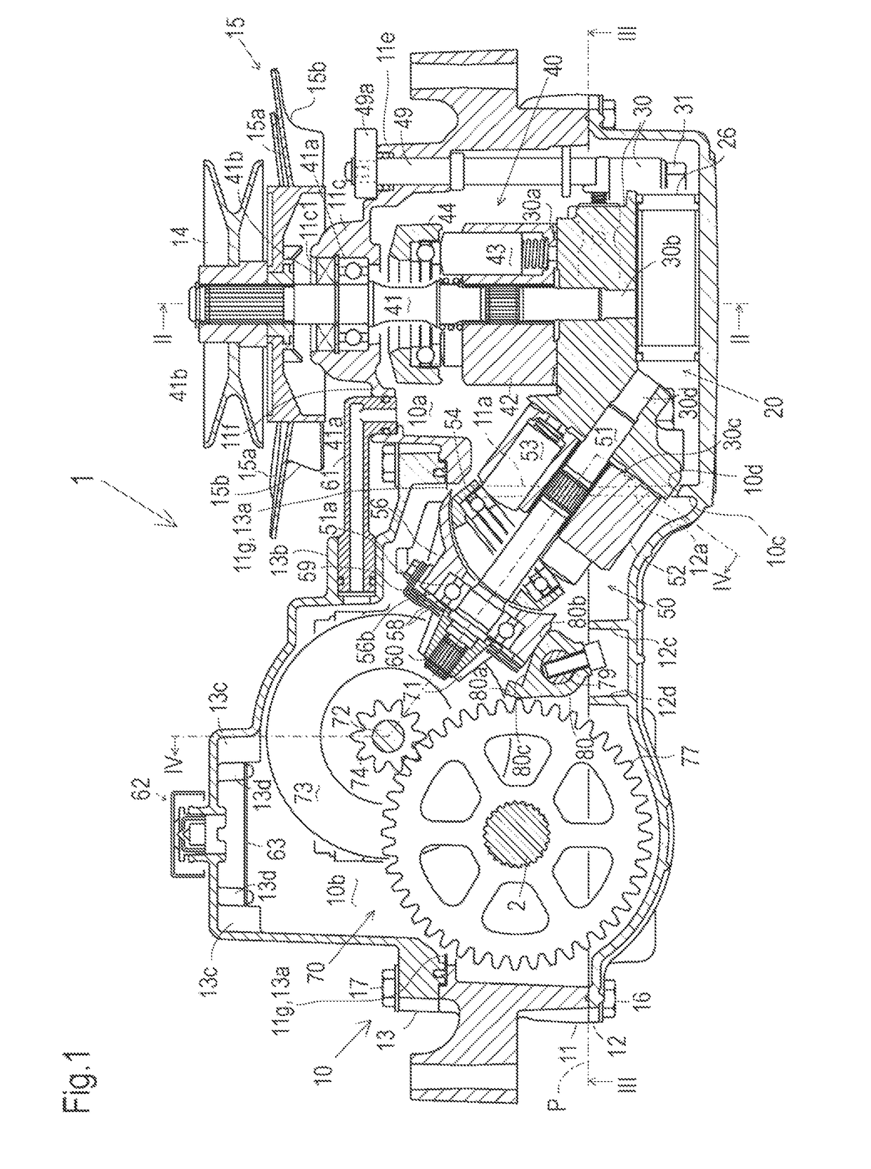
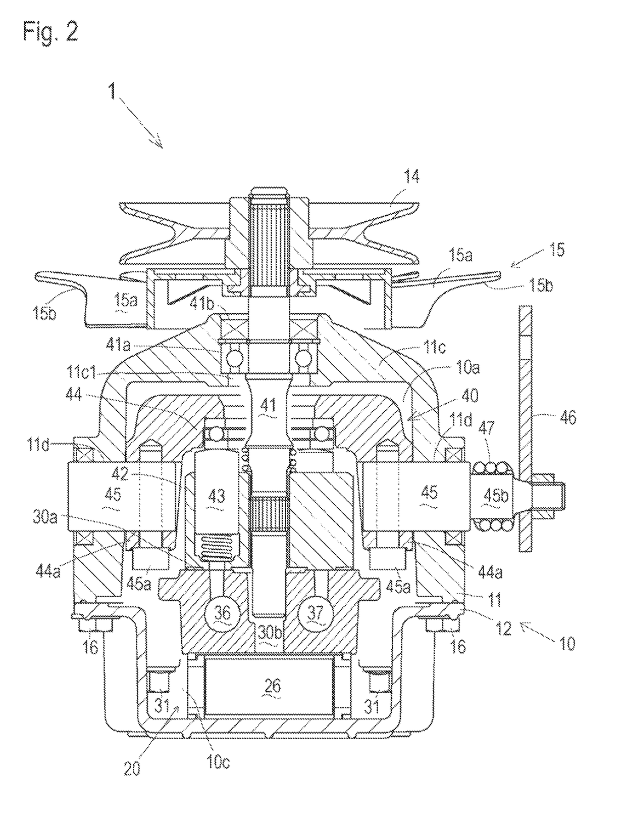
[0026]Referring to FIGS. 1 to 6, a transaxle 1 carrying an axle 2 will be described. Transaxle 1 includes a transaxle casing 10, an HST 20 disposed in a front portion of transaxle casing 10, an axle 2 (serving as either a right or left axle of a vehicle) journalled by a rear portion of transaxle casing 10, and a reduction gear train 70 disposed in the rear portion of transaxle casing 10 so as to drivingly connect HST 20 to axle 2. Alternatively, transaxle 1 may be located to have HST 20 in the rear portion thereof and to have reduction gear train 70 and axle 2 in the front portion thereof. However, the following description will be given on the assumption that HST 20 is in the front portion, and reduction gear train 70 and axle 2 in the rear portion.

[0027]Transaxle casing 10 includes a main housing 11, a bottom housing 12, and a top housing 13. Main housing 11 and bottom housing 12 abut against each other at a horizontal joint plane P and are fastened together by bolts 16. Main hous...


PUM


Abstract

A transaxle comprises a hydrostatic transmission (HST), an axle, a gear train interposed between the HST and the axle, a casing and a partition. The casing defines an HST chamber and a gear chamber. The HST is disposed in the HST chamber. The gear train and the axle are disposed in the gear chamber. The partition is disposed in the casing so as to separate the HST chamber and the gear chamber from each other. The partition has an opening through which a hydraulic motor of the HST passes to extend from the HST chamber into the gear chamber so as to be drivingly connected to the gear train. The partition obstructs a flow of fluid between a fluid sump in the HST chamber from a fluid sump in the gear chamber.

Description

BACKGROUND OF THE INVENTION[0001]Field of the Invention[0002]The invention relates to a transaxle including a hydrostatic transmission (hereinafter “HST”).[0003]Related Art[0004]Conventionally, as disclosed in U.S. 2015 / 0007555 A1, there is a well-known transaxle including a casing that carries an axle and that incorporates an HST and a gear train interposed between the HST and the axle. The HST includes a center section settled on a bottom of the casing via a fluid filter, a vertical axial hydraulic pump mounted on the center section, and a vertically slant axial hydraulic motor mounted on the center section.[0005]A cavity of the casing has front and rear portions. One of the front and rear portions of the cavity serves as an HST chamber accommodating the HST, and the other of the front and rear portions of the cavity serves as a gear chamber accommodating the gear train and the axle. The hydraulic motor having a vertically and fore-and-aft slant axis is extended from the HST chamb...

Claims


Application Information

Patent Timeline
Patent Type & Authority Patents(United States)
IPC IPC(8): F16D31/00F16H57/02F16H47/00B60K17/10F16H57/04
CPCF16H57/0457B60K17/105F16H57/02
Inventor YASUDA, TOSHIFUMIMURASHIMA, DAISUKEIWAKI, KOJIMAEHARA, HIROKIYAMANE, KOGA
Owner KANZAKI KOKYUKOKI MFG
Why Eureka
Try Eureka