System for transferring ions in a mass spectrometer

a mass spectrometer and ion transmission technology, applied in the field of ion optics for mass spectrometers, can solve the problems of limiting the overall sensitivity of the mass spectrometer, unsuitable vacuum inside the mass spectrometer for mass analysis, and limiting the pumping requirements of skilled in the art, so as to improve the overall ion transmission efficiency, and reduce the pumping requirements

Active Publication Date: 2017-09-12
THERMO FINNIGAN
View PDF35 Cites 12 Cited by
  • Summary
  • Abstract
  • Description
  • Claims
  • Application Information

AI Technical Summary

Benefits of technology

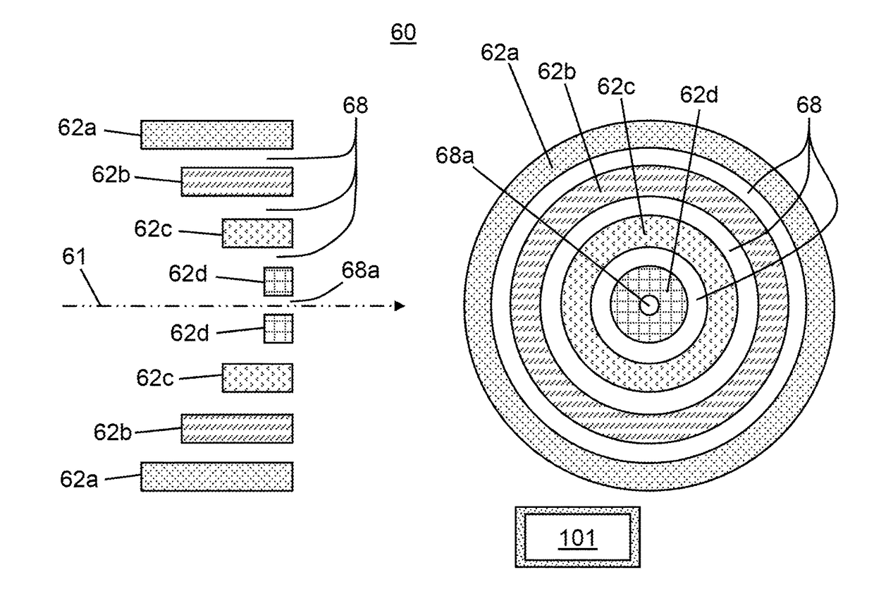
[0028]In accordance with the present teachings, various ion transport systems are disclosed that include an ion transfer tube having one or more internal bores with an obround or slotted cross section. The ion transfer tube is configured so as to deliver ions to, in some embodiments, a conventional ion funnel or a stacked ring ion guide. Alternatively, the ion transfer tube may be configured to deliver ions to an open geometry funnel which allows separation of ions that are retained by the RF field from the gas stream that flows through gaps between the ring electrodes so as to be pumped away, by the vacuum pump connected to the vacuum chamber that houses the device. This configuration allows for a better control of the pressure within the device and improved overall ion transmission efficiency while limiting pumping requirements. The ion transfer tube is oriented such that the long dimension (i.e., the width) of its bore is within or oriented substantially parallel to or approximately parallel to a plane defined by and containing the axis of the ion transfer tube and an ion channel axis. The ion channel axis may be the central axis of either the ion funnel, or may be an ion channel axis of a stacked ring ion guide or an alternative open-geometry funnel device comprising the plurality of electrodes. The long dimension of the ion transfer tube bore or slot is considered to be “approximately parallel” to a plane, as that term is used in this document, when the long dimension makes an angle, with respect to the plane, of thirty degrees (30°) or less. The long dimension of the ion transfer tube bore or slot is considered to be “substantially parallel” to a plane, as that term is used in this document, when the long dimension makes an angle, with respect to the plane, of one degree (1°) or less. The ions and gas emitted from the ion transfer tube are delivered to the ion transport device. The gas emitted from the non-round bore expands as an asymmetric plume. By either offsetting the axis of the ion transfer tube from the axis of the ion channel of the ion transport device or positioning the tube such that its axis is at an angle to the axis of the ion channel of the ion transport device, the plume can be caused to impinge on the electrode plates in such a fashion that most of the gas is diverted away from a downstream evacuated chamber, such as a mass analyzer chamber. Gaps between electrode plates or additional apertures within the electrode plates may be configured with a position and shape so as to match the position and shape of the gas plume, thus exhausting the gas from the ion transport apparatus or system into an enclosing chamber from which it may be efficiently pumped away.
[0033]In some embodiments, the ion transfer tube may be configured such that the ion transfer tube axis is parallel to and offset from the axis of an ion channel of an associated ion transport apparatus. In other embodiments, the ion transfer tube may be configured such that the ion transfer tube axis is disposed substantially at ninety degrees relative to the ion channel axis. In some embodiments, the ion transfer tube comprises two or more parallel internal bores or slots. In some embodiments, a dimension or cross sectional area of an internal bore or slot of the ion transfer tube may decrease along the length of the ion transfer tube in a direction from a tube inlet to a tube outlet.

Problems solved by technology

Thus, those skilled in the art are continually confronted with challenges associated with transporting ions and other charged particles generated at atmospheric or near atmospheric pressures, and in many cases contained within a large gas flow, into regions maintained under high vacuum.
But limiting gas conductance also severely restricts ion sampling from the API source into the mass spectrometer and limits the overall sensitivity of the mass spectrometer (Bruins, A. P., “Mass spectrometry with ion sources operating at atmospheric pressure”, Mass Spectrom. Rev., 1991, 10(1), pp.
Unfortunately, an increase in the conductance can render the vacuum inside the mass spectrometer unsuitable for mass analysis.
The dependence of C on the fourth power of the diameter, D, implies that a subtle increase in conductance will yield excessive gas load for the vacuum pumps.
Over time, the continued build up of these deposited contaminants can cause electrical arcing across the closely spaced electrodes and can change the electrical permittivity of ion lenses, which in turn reduces ion transmission.
As a result, mass spectrometers that employ such ion transport devices require occasional time-consuming disassembly and cleaning of these devices.
The disassembly and cleaning steps caused by the impingement of gas onto the electrodes may be complicated by the presence of insulator boards 57 and their associated wires or other electronic components
However, the above-noted problem of deposition of neutrals on electrodes can be exacerbated when ion transfer tubes are simply increased in inner diameter in this fashion.
Firstly, more gas will flow from the atmosphere into the mass spectrometer, which will increase the pressures in each of the downstream pumping stages. At some point, the pressures can exceed those essential for the proper functioning of the radio frequency (RF) ion guides in each chamber causing a poor radial confinement and axial propulsion of ions towards the detector.
Secondly, increasing the inner diameter of the capillary bore will reduce the amount of heat transfer from the body of the capillary to the flow stream. This contributes to poor de-solvation, depressed analyte response, and elevated chemical noise.
However, signal losses caused by the additional pumping stage (or stages) and increases in chemical noise due to poor de-solvation have made such practice difficult and costly.
Unfortunately, the practice of offsetting the increased gas load of a wider bore ion transfer tube by increasing pumping capacity or the number of pumping stages (i.e., intermediate-vacuum chambers) so as to maintain a functional vacuum inside the mass spectrometer is generally seen as complicated and costly.
Further, the approach of increasing the throughput of the conventional round-bore ion transfer tube 15, either by shortening it or increasing its inner diameter, has been found experimentally to be limited by how well the solvent surrounding the ions can be evaporated during the transfer time of the tube.
However, the maximum temperature that can be applied to the ion transfer tube is limited due to melting of nearby plastic parts as well as to fragmentation of fragile molecular ions such as certain peptides that may flow through the tube.
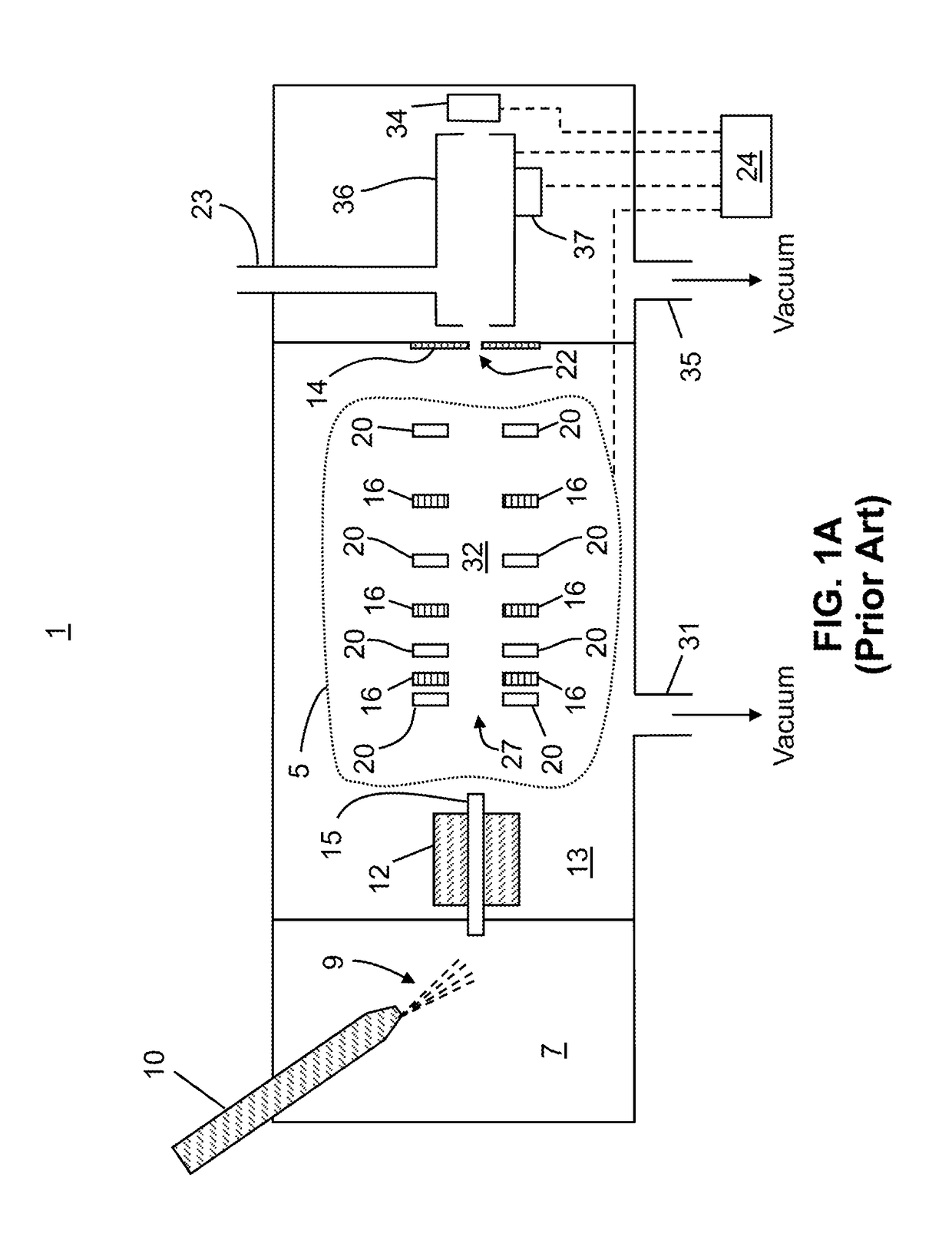
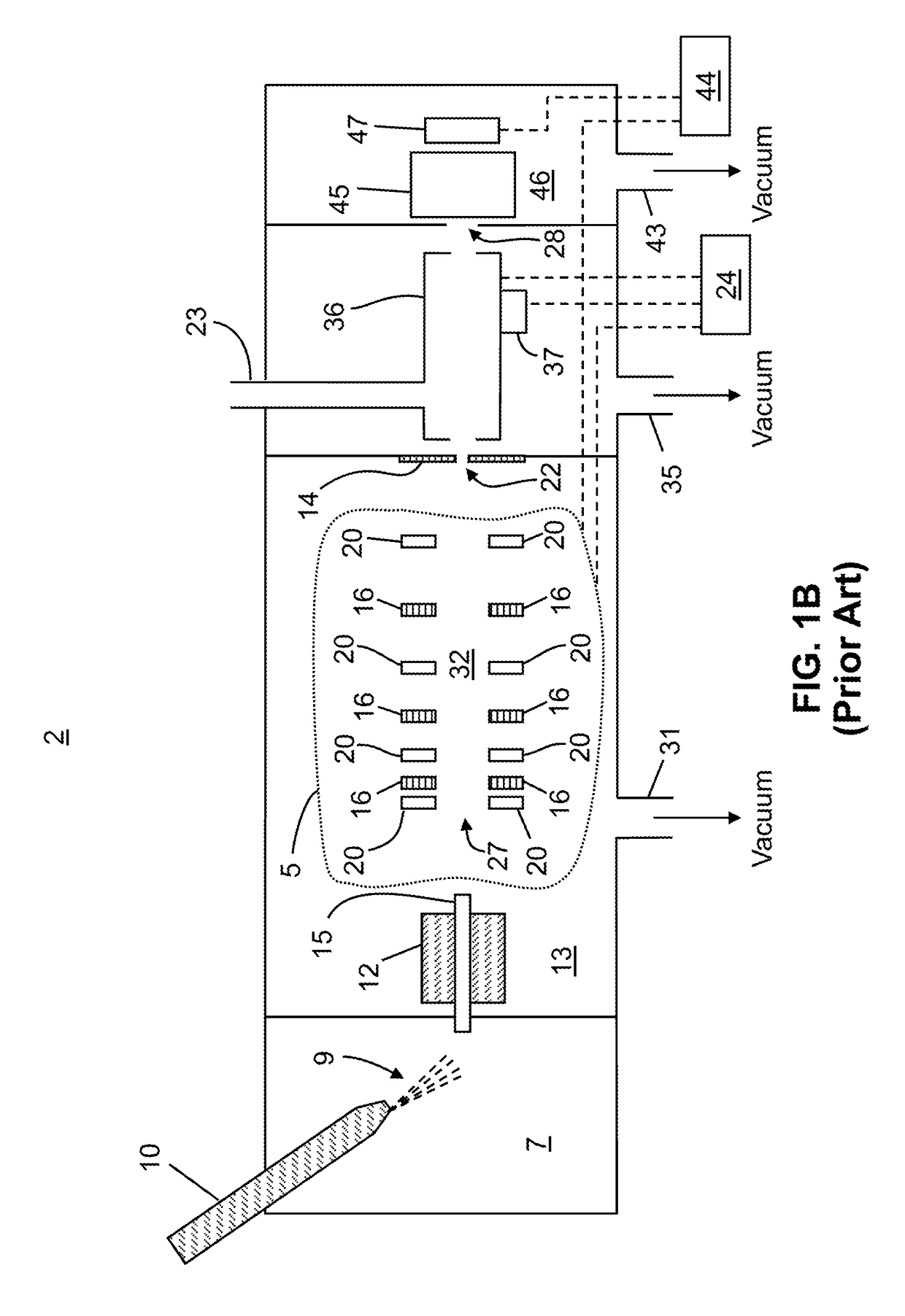
As a result of this multiple parallel plate construction, high velocity gas from the expansion out of the ion transfer tube cannot easily escape the ion transport apparatus so that it can be pumped away.
Consequently, gas pressure may increase to an undesirable level in the chamber containing the ion transport device.
The internal pressure increase may be especially serious in the case of ion-funnel-type ion transport apparatuses, since the projection of the funnel along its symmetry axis shows or presents only the orifice at the end as an opening for escaping gas.
This has negatively affected the ion transmission efficiency of the ion funnel or stacked ring ion guide and, although operation at higher RF frequencies can help to alleviate this problem, reducing the pressure within the device itself is a better solution if one wants to keep increasing the throughput from the atmospheric pressure ionization source.
In addition, the robustness of the device (as measured by the useful operational time between necessary cleanings) is limited by the beam impacting on the electrodes opposite the transfer tube.

Method used


Image

  • System for transferring ions in a mass spectrometer
  • System for transferring ions in a mass spectrometer
  • System for transferring ions in a mass spectrometer

Examples


Embodiment Construction

[0066]The following description is presented to enable any person skilled in the art to make and use the invention, and is provided in the context of a particular application and its requirements. Various modifications to the described embodiments will be readily apparent to those skilled in the art and the generic principles herein may be applied to other embodiments. Thus, the present invention is not intended to be limited to the embodiments and examples shown but is to be accorded the widest possible scope in accordance with the features and principles shown and described. The particular features and advantages of the invention will become more apparent with reference to the appended figures taken in conjunction with the following description.

[0067]FIGS. 5A-5B provide schematic illustrations of a first ion transport apparatus that may be employed in systems in accordance with the present teachings. The ion transport apparatus illustrated in FIGS. 5A-5B in the Applicant's U.S. Pa...


PUM


Abstract

A system for transporting ions includes: an ion transfer tube having an axis and an internal bore having a width and a height less than the width; and an apparatus comprising a plurality of electrodes, each having a respective ion aperture having an aperture center, the apertures defining an ion channel configured to receive the ions from the ion transfer tube and to transport the ions to an outlet end of the apparatus, wherein at least a subset of the apertures progressively decrease in size in a direction towards the apparatus outlet end, wherein the ion transfer tube is configured such that the ion transfer tube axis is non-coincident with an axis of the ion channel or such that the width dimension of the ion transfer tube bore is parallel to a plane defined by the ion transfer tube axis and the ion channel axis.

Description

CROSS REFERENCE TO RELATED APPLICATION[0001]This application claims, under 35 U.S.C. §119(e), the benefit of the filing date of commonly-owned U.S. Provisional Application for Patent No. 62 / 154,557, filed on Apr. 29, 2015 and titled “System for Transferring Ions in a Mass Spectrometer,” said Provisional Application hereby incorporated by reference herein in its entirety.FIELD OF THE INVENTION[0002]The present invention relates generally to ion optics for mass spectrometers, and more particularly to a system for transferring ions from one or more atmospheric-pressure or near-atmospheric-pressure ion sources to an evacuated or lower-pressure region.BACKGROUND OF THE INVENTION[0003]Mass spectrometry analysis techniques are generally carried out under conditions of high vacuum. However, various types of ion sources used to generate ions for MS analyses operate at or near atmospheric pressures. Thus, those skilled in the art are continually confronted with challenges associated with tran...

Claims


Application Information

Patent Timeline
Patent Type & Authority Patents(United States)
IPC IPC(8): H01J49/06
CPCH01J49/066
Inventor WOUTERS, ELOY R.PRASAD, SATENDRADUNYACH, JEAN-JACQUES
Owner THERMO FINNIGAN
Why Eureka
Try Eureka