Elastic membrane, substrate holding device, and polishing apparatus

a technology of substrate holding and polishing apparatus, which is applied in the direction of grinding machines, manufacturing tools, lapping machines, etc., can solve the problems of insufficient polishing or overpolishing, shallow depth of focus, and poor film coverage (step coverage) with respect to a step shape in thin film formation, etc., to achieve suppress the expansion of the side wall to the outside, and easy pressure control of the pressure chamber

Active Publication Date: 2018-10-18
EBARA CORP
View PDF6 Cites 6 Cited by
  • Summary
  • Abstract
  • Description
  • Claims
  • Application Information

AI Technical Summary

Benefits of technology

[0030]According to the present invention, a pressure in the pressure chamber is controlled, whereby a pressing force of the contact portion can be controlled within a narrow range in the outer peripheral end portion. Further, since the first partition wall and the second partition wall linearly extend, the first partition wall and the second partition wall are less likely to come in contact with each other, and therefore pressure control of the pressure chamber can be easily performed. Even if the pressure in the edge pressure chamber becomes high, expansion of the side wall to the outside can be suppressed because the first partition wall linearly extends from the side wall.

Problems solved by technology

Therefore, film coverage (step coverage) with respect to a step shape in thin film formation becomes worse as the total number of multilayer interconnection increases.
In addition, the depth of focus becomes shallow with the miniaturization of photolithography.
Therefore, the planarization processing needs to be performed on a surface of a semiconductor device so that an uneven step in the surface of the semiconductor device falls within the depth of focus.
In the case where a relative pressing force between the wafer being polished and the polishing surface of the polishing pad is not uniform over the entire surface of the wafer, insufficient polishing or overpolishing occurs depending on the pressing force applied to each part of the wafer.

Method used


Image

  • Elastic membrane, substrate holding device, and polishing apparatus
  • Elastic membrane, substrate holding device, and polishing apparatus
  • Elastic membrane, substrate holding device, and polishing apparatus

Examples


Embodiment Construction

[0070]Hereinafter, embodiments of the present invention will be described with reference to the drawings. Note that the embodiments described below are merely examples for implementing the present invention, and the present invention is not limited to specific constitutions described below. In implementing the present invention, a specific constitution according to an embodiment may be appropriately adopted.

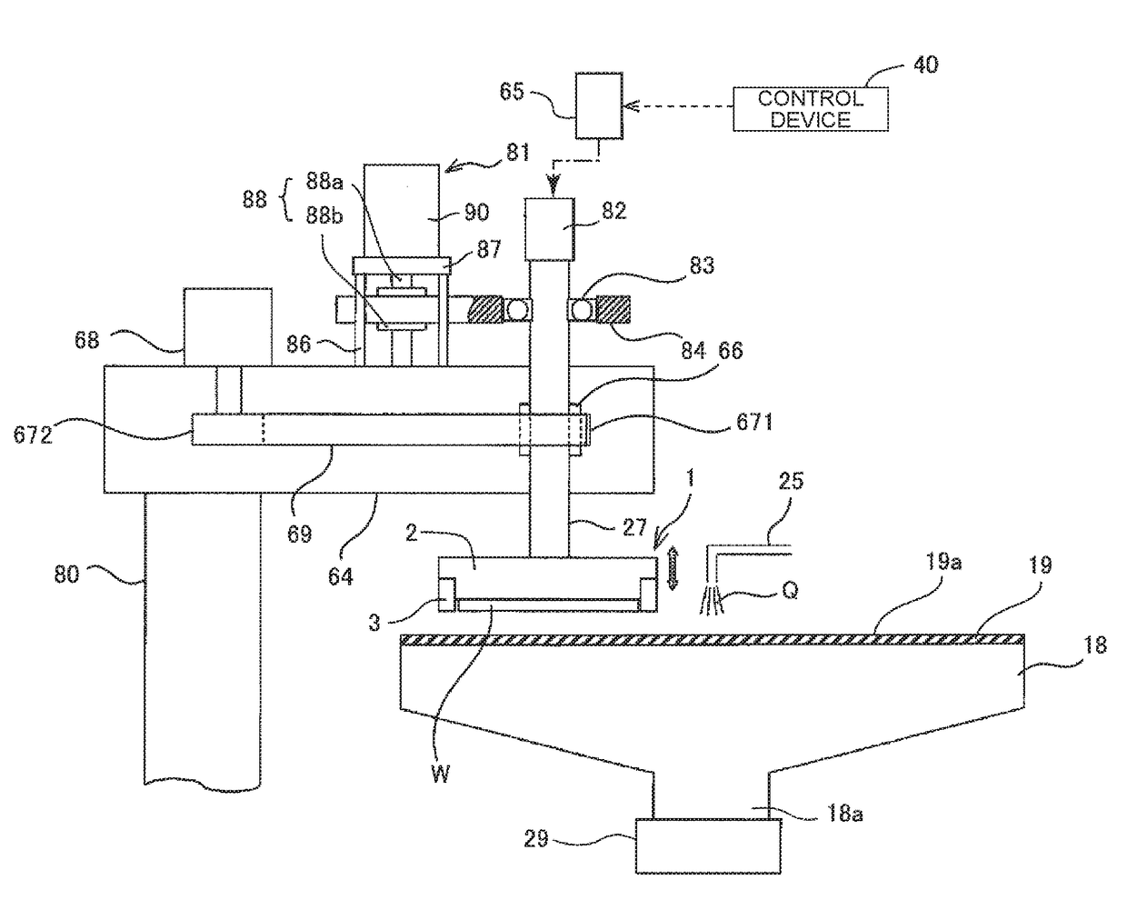
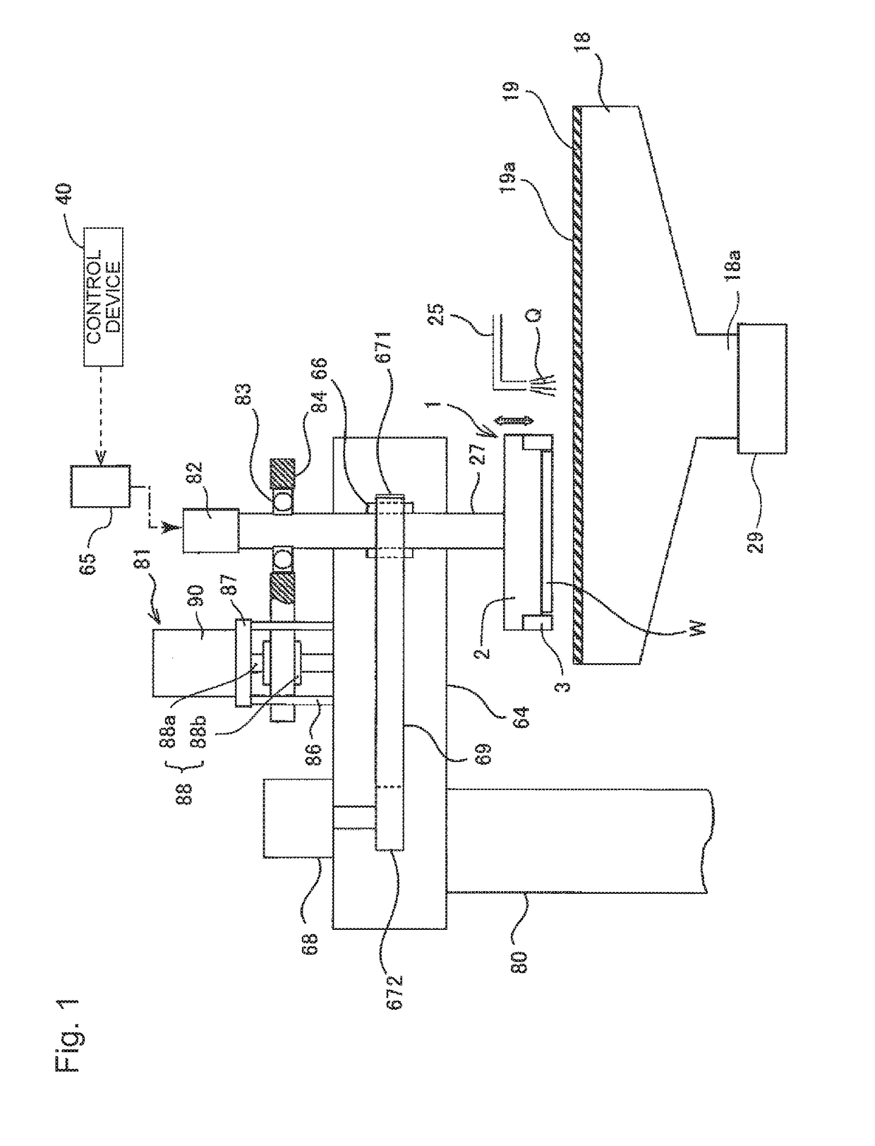
[0071]FIG. 1 is a view illustrating a polishing apparatus according to an embodiment. As illustrated in FIG. 1, the polishing apparatus includes a polishing table 18 that supports a polishing pad 19, and a substrate holding device 1 that holds a wafer W as an example of a substrate that is an object to be polished and presses the wafer W against the polishing pad 19 on the polishing table 18. In the following description, the substrate holding device 1 is referred to as a polishing head 1.

[0072]The polishing table 18 is connected via a table shaft 18a to a table motor 29 disposed...


PUM


Abstract

An elastic membrane to be used for a polishing head includes a contact portion configured to come into contact with a wafer, an annular side wall provided to stand on an outer peripheral end of the contact portion, a first partition wall linearly extending inward in a radial direction in sectional view from the side wall, and a second partition wall linearly extending inward and upward in the radial direction in sectional view from an outer peripheral end portion of the contact portion, wherein the first partition wall, the second partition wall, and the side wall constitute an edge pressure chamber for pressing an edge of the wafer.

Description

CROSS REFERENCE TO RELATED APPLICATION[0001]This nonprovisional application is based on Japanese Patent Application No. 2018-042410 filed with the Japan Patent Office on Mar. 8, 2018 and Japanese Patent Application No. 2017-078933 filed with the Japan Patent Office on Apr. 12, 2017, the entire contents of which are hereby incorporated by reference.FIELD[0002]The present invention relates to a polishing apparatus for polishing a substrate such as a wafer, a substrate holding device for holding the substrate in the polishing apparatus, and an elastic membrane used for the substrate holding device.BACKGROUND AND SUMMARY[0003]In recent years, interconnection of circuits has become finer and the total number of multilayer interconnection is also increasing with realization of higher integration and higher density of semiconductor devices. When realizing multilayer interconnection while achieving miniaturization of a circuit, a step becomes larger by following surface unevenness of a lowe...

Claims


Application Information

Patent Timeline
Patent Type & Authority Applications(United States)
IPC IPC(8): H01L21/687B24B7/04
CPCH01L21/68707B24B7/04B24B37/107B24B37/30
Inventor YAMAKI, SATORUFUKUSHIMA, MAKOTONAMIKI, KEISUKENABEYA, OSAMUTOGASHI, SHINGOOWADA, TOMOKOKATO, YOSHIKAZU
Owner EBARA CORP
Why Eureka
Try Eureka