Oil pump and control method of engine lubrication system of oil pump

An oil pump and low-pressure oil technology, which is applied to the pressure lubrication of the lubricating pump and controlling the pressure of the lubricant, can solve the problems of unstable oil pressure control, increase the engine cost, increase the driving torque of the oil pump, etc., and reduce friction Loss of power consumption, shortened response time, improved pressure control effect

Active Publication Date: 2014-05-21
CHERY AUTOMOBILE CO LTD
View PDF6 Cites 6 Cited by
  • Summary
  • Abstract
  • Description
  • Claims
  • Application Information

AI Technical Summary

Problems solved by technology

[0005] like image 3 As shown, one is that the pressure relief valve of the oil pump controls the oil pressure before the engine filter. The existing problem is that due to the influence of the filter resistance of the oil filter, the oil pressure control of the entire engine system is unstable and is too high. The engine oil pressure will inevitably increase the driving torque of the engine oil pump, and the power of the engine will be seriously wasted; at the same time, high speed will easily cause excessive oil pressure in some parts of the engine, which puts forward high requirements on the strength of the engine components, and also Raised the cost of the engine
But the problem is that after the pressure relief valve adjusts the pressure, it first passes through the high-pressure oil chamber, then through the oil filter, oil cooler, and then to the main oil passage; the reaction time is longer, which increases the pulsation of the engine oil pressure, Unstable oil pressure control in the engine lubrication system

Method used


Image

  • Oil pump and control method of engine lubrication system of oil pump
  • Oil pump and control method of engine lubrication system of oil pump
  • Oil pump and control method of engine lubrication system of oil pump

Examples


Embodiment Construction

[0022] The specific implementation manner of the present invention will be described in further detail below by describing the embodiments with reference to the accompanying drawings.

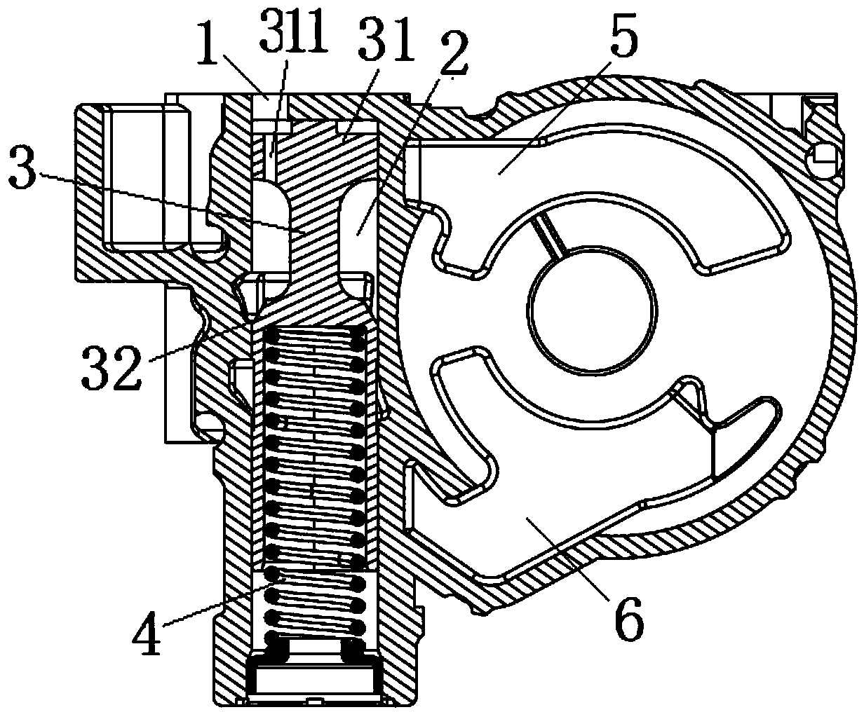
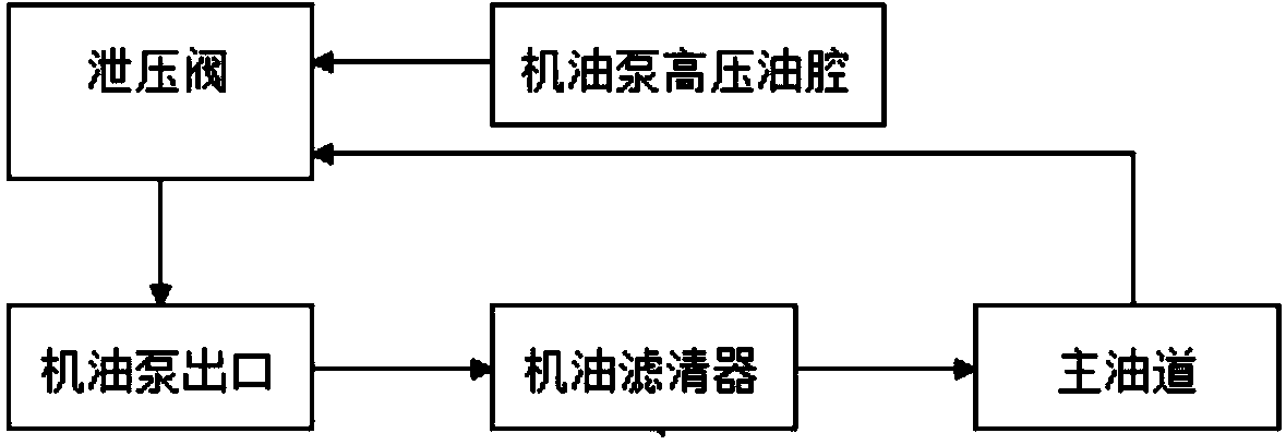
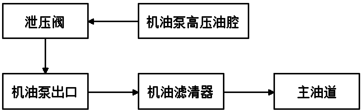
[0023] Such as figure 1 As shown, the oil pump of the present invention includes a high-pressure oil chamber 5 of the oil pump, a low-pressure oil chamber 6 of the oil pump, a pressure relief valve, and a feedback oil passage 1 connected to the main oil passage after the machine filter, wherein the low-pressure oil chamber 6 of the oil pump As a pressure relief chamber, the pressure relief valve controls and regulates the pressure at the outlet of the oil pump to ensure the stable operation of the engine lubrication system under the required pressure.

[0024] The pressure relief valve includes a plunger chamber 2, a plunger 3 and a spring 4 located in the plunger chamber 2, and the pressure relief valve is combined by the pressure of the high-pressure oil chamber 5 of the engine oil pump and ...


PUM


Abstract

The invention discloses an oil pump and a control method of an engine lubrication system of the oil pump. The oil pump comprises an oil pump high-pressure oil cavity, an oil pump low-pressure oil cavity, a plunger cavity connected with the oil pump high-pressure oil cavity and a feedback oil way connected with an oil filter rear main way oil way, a plunger and a spring are arranged in the plunger cavity, the feedback oil way is communicated with the plunger cavity, one end of the plunger is a first plunger head, the other end of the plunger is a second plunger head, the first plunger head separates the feedback oil way from the oil pump high-pressure oil cavity, the second plunger head is connected with the spring, and the first plunger head is provided with a plunger hole used for enabling the feedback oil way and the oil pump high-pressure oil cavity to be communicated. The control method comprises the following steps that a pressure relief valve of the oil pump is controlled to work jointly by the pressure of the oil pump high-pressure oil cavity and the pressure fed back by the oil filter rear main way oil way. According to the oil pump and the control method of the engine lubrication system of the oil pump, pressure control of the whole engine lubrication system is improved, the pressure of oil of the engine can be accurately controlled, and the pulsation of the pressure of the oil is reduced.

Description

technical field [0001] The invention relates to the technical field of engine lubrication, in particular to an oil pump and a method for controlling the engine lubrication system thereof. Background technique [0002] The working principle of the engine lubrication system is: the oil pumped by the oil pump passes through the oil filter and oil cooler and then enters the main oil passage to lubricate the components; the oil pump provides enough pressure and flow of oil for the entire engine to ensure that each friction The parts are fully lubricated and the relevant pressure-bearing parts are protected. [0003] Normally, the amount of oil discharged by the oil pump is proportional to the engine speed. When the engine speed increases, the amount of oil discharged from the oil pump increases proportionally. In fact, the oil supply required by each part of the engine is not directly proportional to the engine speed; at low speeds, the engine oil demand varies greatly; while a...

Claims


Application Information

Patent Timeline
Patent Type & Authority Applications(China)
IPC IPC(8): F01M1/02F01M1/16
Inventor 牛晨晓张勇琚雪明
Owner CHERY AUTOMOBILE CO LTD
Why Eureka
Try Eureka