Electrical outlet unit

a technology of electrical outlet and charging device, which is applied in the direction of coupling device connection, instruments, horology, etc., can solve the problems of increasing nonrenewable carbon based resources such as coal, oil and natural gas, and charging device consumption no power,

Inactive Publication Date: 2017-09-12
MILLER DENNIS L +1
View PDF9 Cites 34 Cited by
  • Summary
  • Abstract
  • Description
  • Claims
  • Application Information

AI Technical Summary

Benefits of technology

[0009]Unlike prior art devices, the present electrical outlet unit allows the user to specify the period of time that the electrical outlet unit provides power to the battery charger. One version of the present electrical outlet unit allows the user to select a charge maintaining state, in which the device provides power to the charger for 20 minutes out of every 72 hours. In another version, the electrical outlet unit may be integrated into an appliance, such as lamp, providing docking bay for charging devices and controlling the duration of the charging. In another version, the electrical outlet unit may have a ground fault interrupter circuit integrated allowing control of the duration of charging for outlets required by code to have this type of protection in place.
[0022]It is another object of the present electrical outlet unit to provide an apparatus that will eliminate the waste of power and nonrenewable resources, through power isolation within the device and device charger's circuit.
[0023]It is another object of the present electrical outlet unit to allow the user to select the amount of time the battery is to be charged.
[0026]It is another object of the present electrical outlet unit for incorporation into appliances, such as lamps, to create a docking bay allowing a user to select the amount of time a connected device having a rechargeable battery is to be charged. As described, the docking bay may have multiple outlets for operating and allowing charging of connected rechargeable devices.

Problems solved by technology

Often the corresponding chargers remain plugged into a power outlet and consume power when the devices are not being used.
This consumed energy has required power plants to accommodate the futile power continuously consumed by the plugged in charger, thus increasing nonrenewable carbon based resources such as coal, oil and natural gas.
When electrical isolation from a battery occurs, the charging device consumes no power.
After charging, a battery slowly loses its charge even when not in use.
Left unattended for long enough, the charge loss would be sufficient to render the battery unusable until such time it was recharged.
The prior art energy saving devices do not allow a user to adjust the charging time, or provide battery maintenance, to match the battery thereby maximizing the energy savings.

Method used


Image

  • Electrical outlet unit
  • Electrical outlet unit
  • Electrical outlet unit

Examples


Embodiment Construction

—BRIEF DESCRIPTION OF THE FIGURES

[0028]In order that the advantages of the invention will be readily understood, a more particular description of the invention briefly described above will be rendered by reference to specific embodiments illustrated in the appended drawings. Understanding that these drawings depict only typical embodiments of the invention and are not therefore to be considered limited of its scope, the invention will be described and explained with additional specificity and detail through the use of the accompanying drawings.

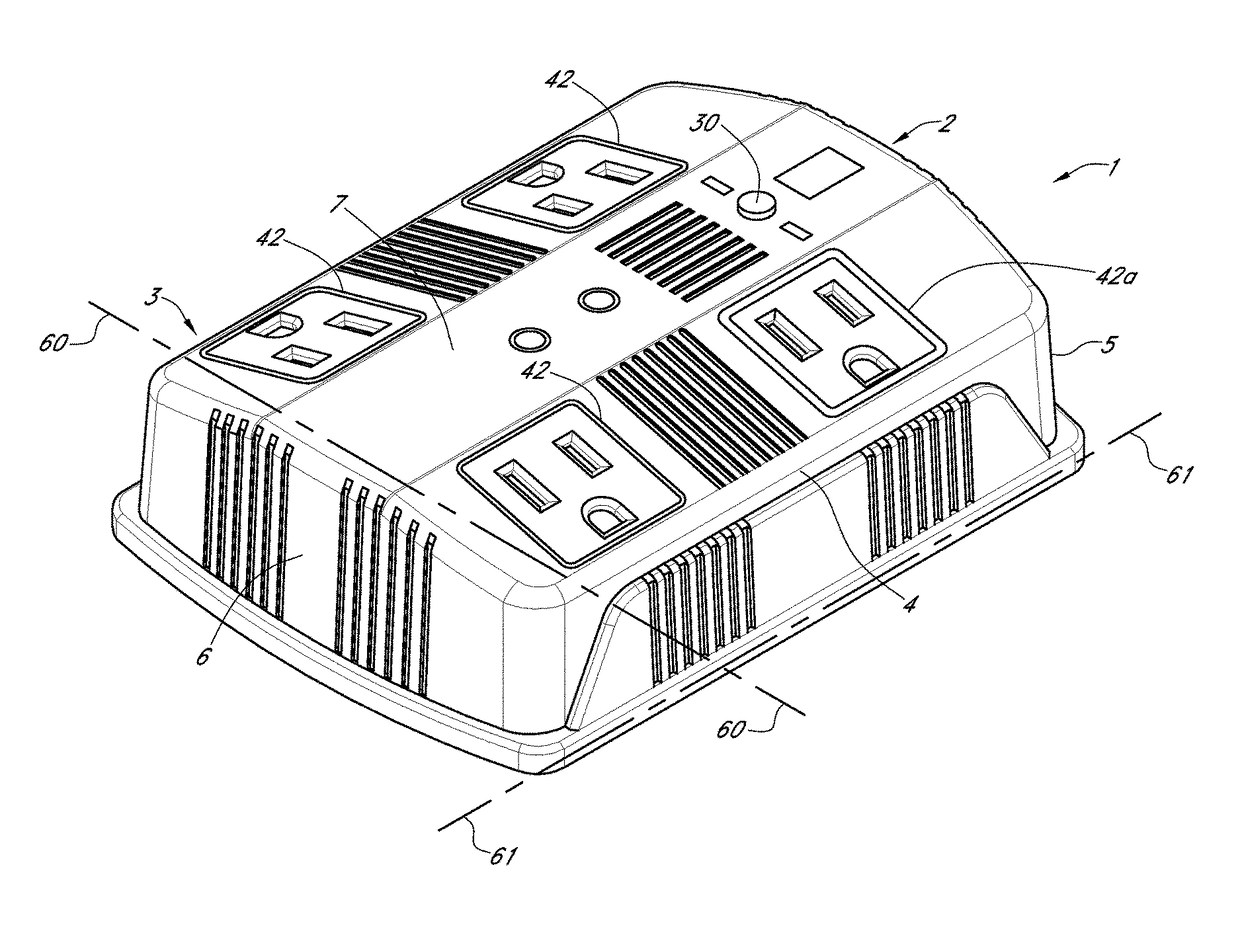
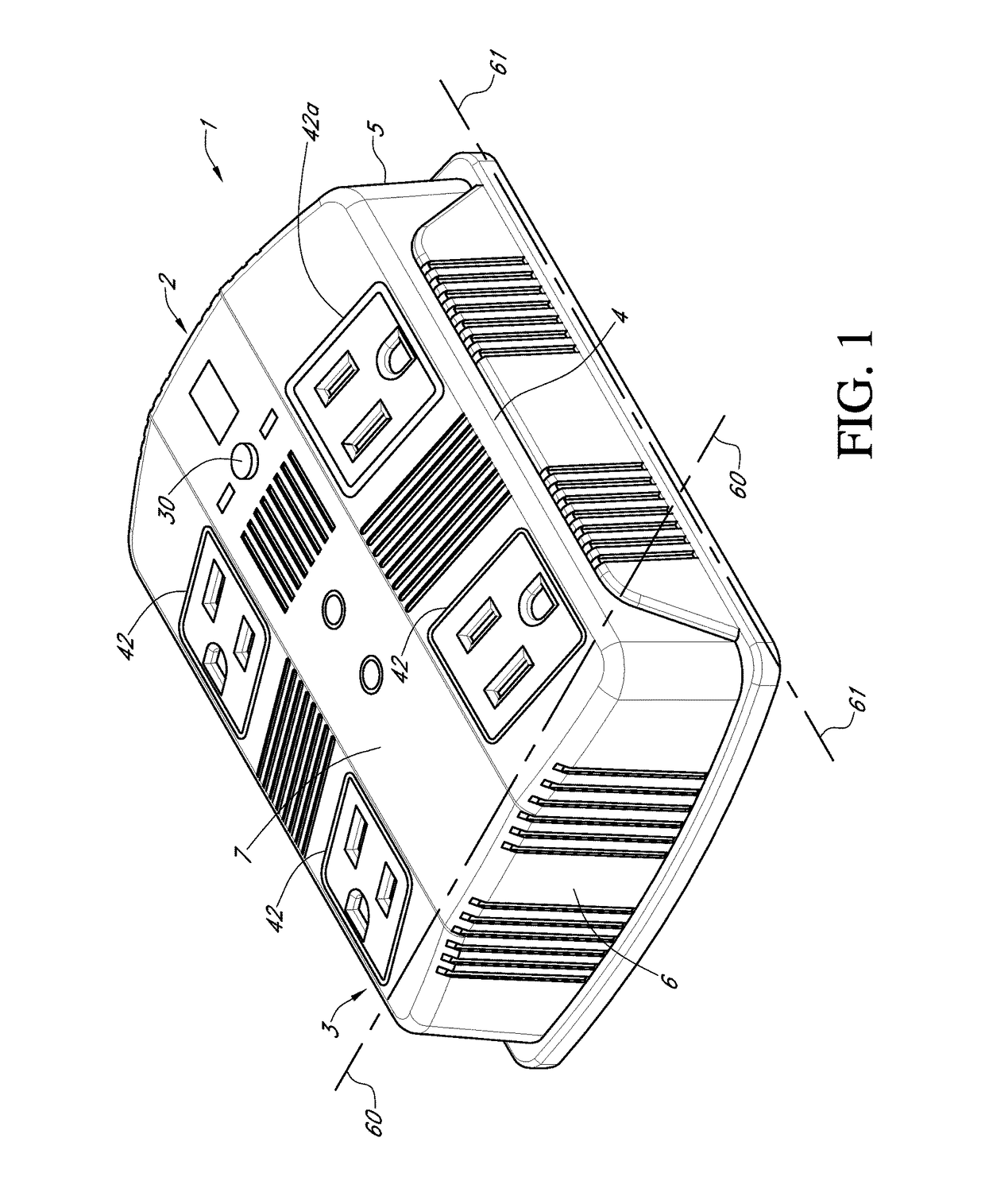
[0029]FIG. 1 is a perspective view of one embodiment of an electrical outlet unit subject of the present patent application.

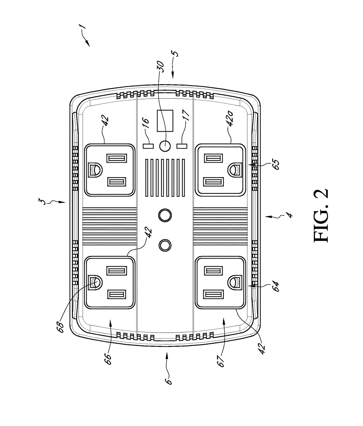
[0030]FIG. 2 is a front view of the electrical outlet unit of FIG. 1.

[0031]FIG. 3 is a side view of the electrical outlet unit of FIG. 1.

[0032]FIG. 4 is a view of the rear side of the electrical outlet unit of FIG. 1

[0033]FIG. 5 is a top view of the electrical outlet unit of FIG. 1.

[0034]FIG. 6 is a front view of another ...


PUM


Abstract

An electrical unit outlet device is disclosed for controlling power isolation, based on a pre-determined time, for a device charger, while remaining plugged into a power outlet. A power isolating circuit cuts any power to the charging device off when charge is complete. Multiple embodiments are disclosed including a ground fault interrupted electrical unit outlet that may be controlled by a timer to shut down after batteries have been charged is disclosed and claimed herein. All circuits will subject to ground fault interruption protection and may be subject to surge protection as well. In another embodiment, a lamp with timed charging outlets that shut down when batteries are being charged is disclosed and claimed herein.

Description

CROSS REFERENCE TO RELATED APPLICATIONS[0001]Applicant claims priority and benefit from provisional U.S. Pat. App. Nos. 61 / 798,338 and 61 / 798,776 both filed on Mar. 15, 2013 under 35 U.S.C. 119. The present application is also a continuation-in-part of and claims priority from U.S. patent application Ser. No. 13 / 903,747 filed on May 28, 2013, which was a continuation of U.S. patent application Ser. No. 12 / 768,724 filed on Apr. 27, 2010, now U.S. Pat. No. 8,471,718 which claimed priority from provisional U.S. Pat. App. No. 61 / 173,001 filed on Apr. 27, 2009. The present application is also a continuation-in-part of and claims priority from U.S. patent application Ser. No. 13 / 043,455, which claimed priority from provisional U.S. Pat. App. Nos. 61 / 311,721 filed on Mar. 8, 2010 and 61 / 317,722 filed on Mar. 26, 2010, all of the preceding applications are incorporated by reference herein in their entireties.FIELD OF INVENTION[0002]The invention is generally directed to an apparatus for mak...

Claims


Application Information

Patent Timeline
Patent Type & Authority Patents(United States)
IPC IPC(8): G08B21/00H02J3/00H01R13/66
CPCH02J3/00H01R13/6666Y10T307/951G04C23/04G04C23/12G04G15/003H01H47/18H01R25/003H01R25/006
Inventor MILLER, DENNIS L.MAY, DWAIN C.
Owner MILLER DENNIS L
Why Eureka
Try Eureka