Electric fence energiser

a technology of energiser and electric fence, which is applied in the direction of self-interrupter, electric variable regulation, ac network voltage adjustment, etc., can solve the problems of insufficient peak pulse voltage of 1200v to effectively deter animals, limited type of energiser, and not very popular type of energiser

Inactive Publication Date: 2006-04-27
TRU TEST
View PDF3 Cites 12 Cited by
  • Summary
  • Abstract
  • Description
  • Claims
  • Application Information

AI Technical Summary

Benefits of technology

[0030] The object of the present invention is to provide an electric fence energiser in which the duration of the output pulse is controlled over a wide range to thereby control output energy.

Problems solved by technology

A peak pulse voltage of 1200V is generally considered insufficient (too low) to effectively deter animals (livestock) from crossing a barrier formed by an electric fence.
This type of energiser is not very popular mostly because it is limited to maximum power levels that are considerably lower than what can be achieved using the capacitor discharge topology.
This type of energiser is limited to very low power levels due to the required high impedance.
Both capacitor discharge type and inductive discharge type energisers tend to be wasteful of energy for many load conditions.
Whilst such energy loss is often not of concern for low- and medium-energy energisers, energy loss in internal circuits can become a problem for high-energy energisers.
Especially in high-energy energisers the step-up transformer is a major source of energy loss due to resistive losses in the copper windings, hysteretic and eddy current losses in the magnetic core and poor inductive coupling of the windings due to saturation of the magnetic core material.
However, whilst the auto-transformer mostly offers an improvement by way of better coupling between the windings, the other losses associated with step-up transformers remain largely or entirely the same and the advantage of improved coupling may be partially lost if the magnetic material of the core becomes saturated during the pulse.
Although capacitor discharge type energisers can be easily made to comply with such safety standards, such energisers still have a limited amount of control over the three pulse parameters energy, current and duration.
The step-up transformer used in conventional energiser designs places a severe restriction on the maximum pulse width that can be achieved, because the magnetic core material tends to become saturated for longer pulse durations.
A limitation of a thyristor and triac is that it is difficult to turn the device off (i.e. revert the device to the non-conducting state) once it is placed in the conducting state.
The difficulty in turning off the switching device therefore is the reason, in most current energiser designs, for a limitation on the minimum pulse duration that the energiser can produce.

Method used


Image

  • Electric fence energiser
  • Electric fence energiser
  • Electric fence energiser

Examples


second embodiment

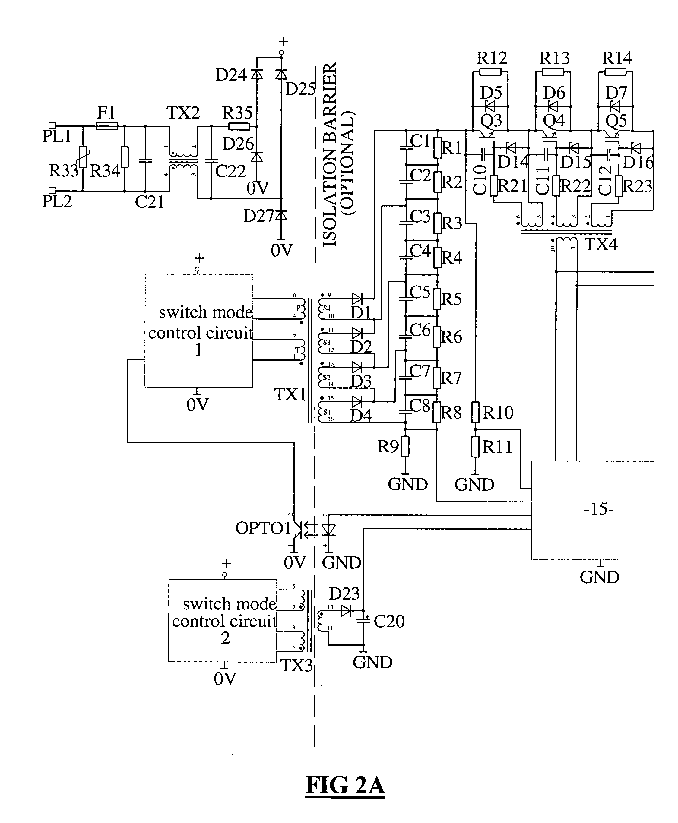
[0045]FIG. 4 is a circuit diagram of an electric fence energiser incorporating the present invention

[0046]FIG. 5 is a circuit diagram as shown in FIG. 4 but illustrating the charging state of the energiser,

[0047]FIG. 6 is similar to FIG. 5 but showing the energiser in a discharge state, and

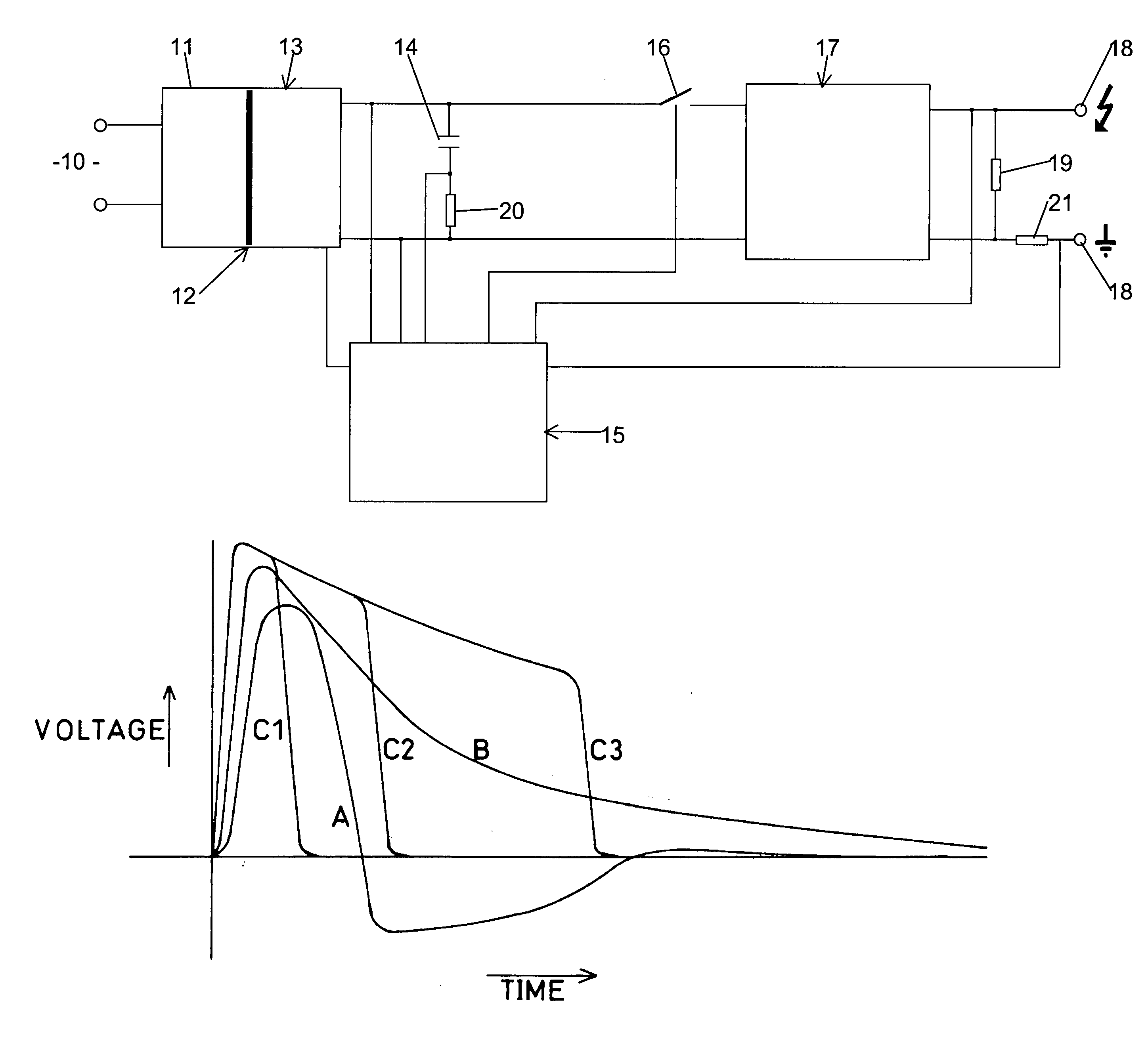
[0048]FIG. 7 is a graphical representation of a possible pulse voltage waveform.

DESCRIPTION OF PREFERRED EMBODIMENTS OF THE INVENTION

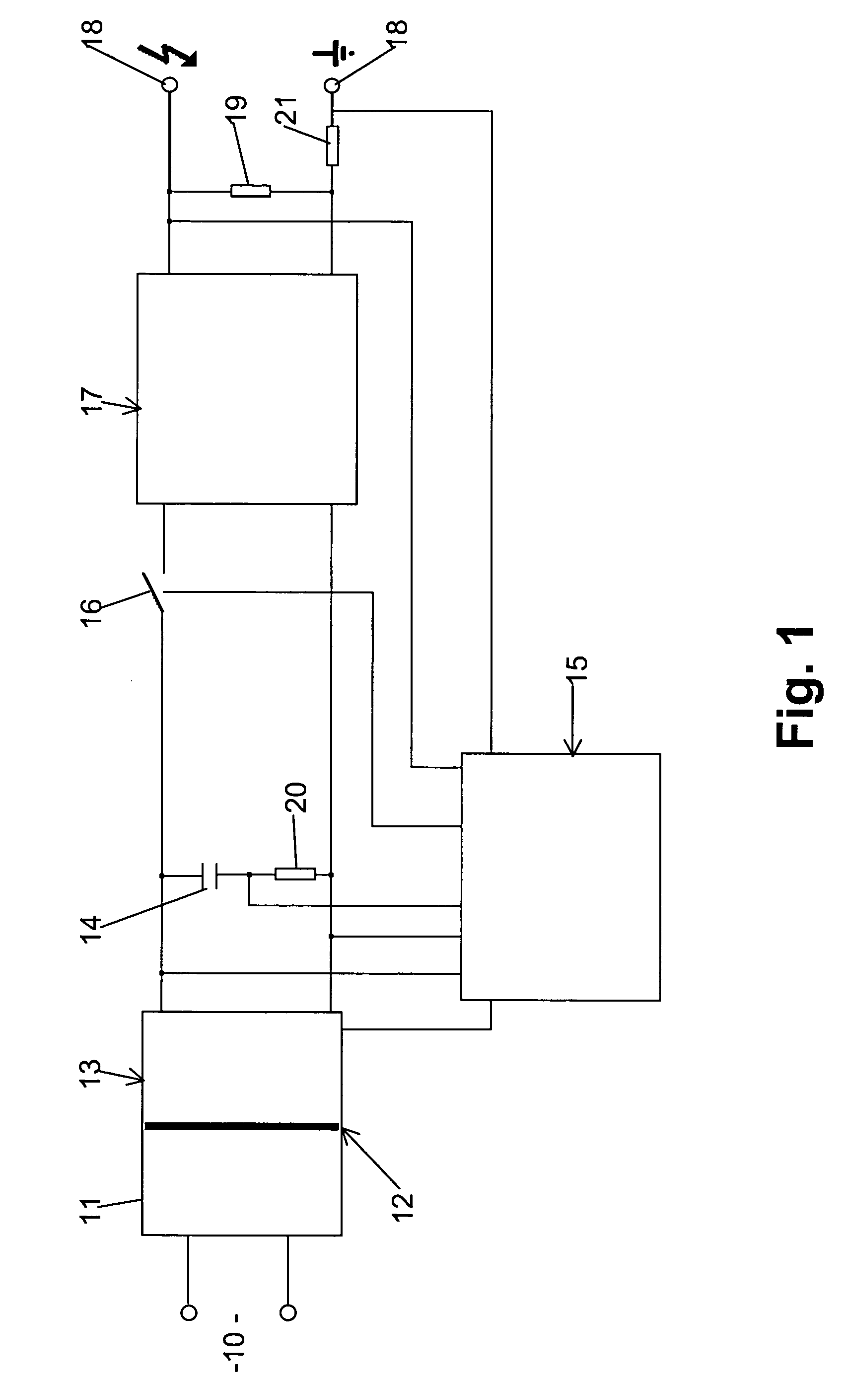
[0049] Referring to FIG. 1 there is shown an electric fence energiser which is powered from an energy source 10, which may be AC mains supply, a battery, solar panel or other source. The power source is connected to power supply circuit 11 which may incorporate an electrical isolation barrier 12. The power supply circuit 11 is coupled to charging circuit 13 which, as shown, has its output connected to a high voltage energy storage capacitor 14. The capacitor 14 is able to be charged up to the required (or desired) output voltage. As previously described, energy st...

first embodiment

[0128] As the charging circuit only has to generate 1000V the design is easier, lower cost and simplified over the This is especially the case with the switching transformer (if employed) which becomes simpler, lower cost and may offer improved reliability. Also other methods of charging the energy storage capacitors can be used e.g. by means of a mains “voltage doubler” circuit.

[0129] With the second embodiment the charging voltage can more easily be generated from a low supply voltage such as 12V or 24V. Thus the voltage can be generated by using battery supply, battery backup and operation from solar panels as well as from mains supply.

[0130] With the second embodiment, each switching transistor can be controlled independently thus it is possible to independently choose to either discharge or not discharge each energy storage capacitor. For example, in a circuit with eight energy storage capacitors each charged up to a voltage of 1000V it is possible to control the peak output ...


PUM


Abstract

An energiser for an electric fence. The energiser includes, at least, one energy storage capacitor (14), a charging circuit (13) to enable the or each storage capacitor (14) to be charged from an energy source (10), semiconductor switching means (16), and control circuit means (15) to facilitate controlled turning -on and -off of the semiconductor switching means (16) to control the duration of the discharge from the energy storage means (14). In one form of the energiser a first semi-conductor switching means is arranged to connect in parallel the energy storage capacitors (14) to be charged and second semi-conductor switching means to connect two or more of the charged energy storage capacitors (14) in series to create an output pulse.

Description

BACKGROUND TO THE INVENTION [0001] This invention relates to an electric fence energiser. [0002] The term energiser in connection with electric fencing is commonly used to indicate a generator of a high voltage output which can be connected to an electric fence to electrify the fence. Other terms used to identify this piece of electric fencing equipment include fence controller, electrifier, charger, pulse generator and the like. [0003] Electric fencing is widely used for the control of livestock animals, game, perimeter security installations and possible other uses. In such installations, the energiser performs the function of supplying a high voltage to one or more conductors of the electric fence with the aim of providing an electric shock to an animal or a person touching one or more of the conductors. The high voltage on the fence conductors may be present in the form of intermittent pulses of short duration, or as a continuous AC or DC voltage. [0004] A significant proportion...

Claims


Application Information

Patent Timeline
Patent Type & Authority Applications(United States)
IPC IPC(8): G05F1/10H02J3/12
CPCH05C1/04
Inventor LUNENBURG, PIETER CORNELISBRYAN WOODHEAD, ROBERT CHARLESMURPHY, JOHN
Owner TRU TEST
Why Eureka
Try Eureka