Thyristor based voltage source converter

a voltage source converter and thyristor technology, applied in the direction of ac-ac conversion, power conversion systems, electrical apparatus, etc., can solve the problems of large footprint, slow control, inability to improve ac grid stability, etc., and achieve the effect of significantly reducing the cost of valves

Active Publication Date: 2017-09-12
HITACHI ENERGY SWITZERLAND AG
View PDF21 Cites 1 Cited by
  • Summary
  • Abstract
  • Description
  • Claims
  • Application Information

AI Technical Summary

Benefits of technology

[0016]The present invention has a number of advantages. Since the converter is a voltage source converter it is possible to control both real and reactive power independently of each other. There is furthermore no requirement of any polarity reversal for power reversal, and thereby the converter can be combined with the use of extruded DC cables. The valve cost is also significantly reduced. The invention also allows a substantial loss reduction to be obtained.

Problems solved by technology

However, LCC converters have a number of shortcomings: they may experience commutation failure, they require a strong alternating current (AC) grid, they do not support reactive power, have high harmonics, require polarity reversal for power reversal, leave a large footprints, are slow in control and unable to improve AC grid stability.
However, VSC converters have the following disadvantages: higher ON state loss, higher switching loss, increased rating (due to fault current), frequent failure and higher cost.
However they also provide a larger footprint (cell capacitors).

Method used


Image

  • Thyristor based voltage source converter
  • Thyristor based voltage source converter
  • Thyristor based voltage source converter

Examples


Embodiment Construction

[0024]In the following, a detailed description of preferred embodiments of the invention will be given.

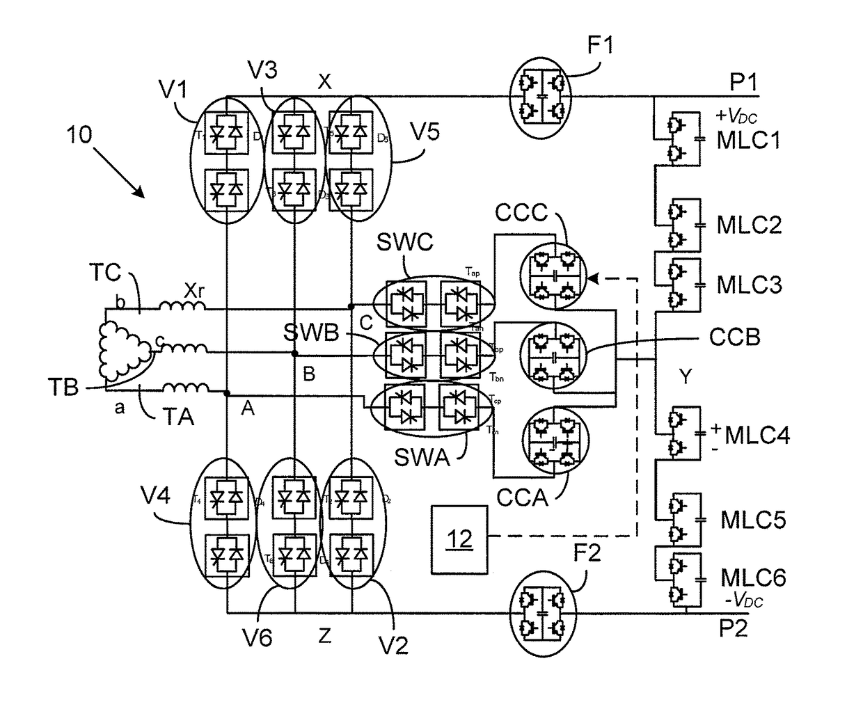
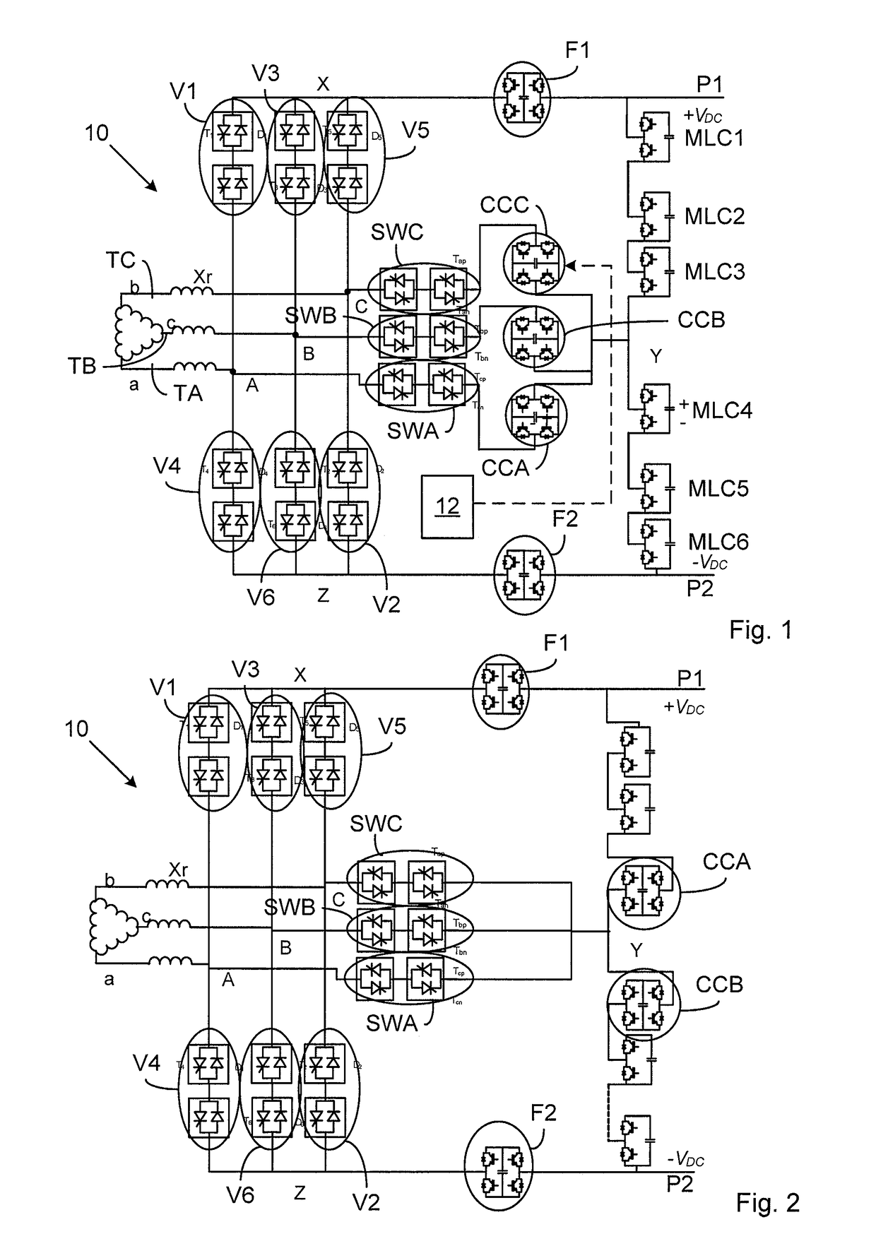
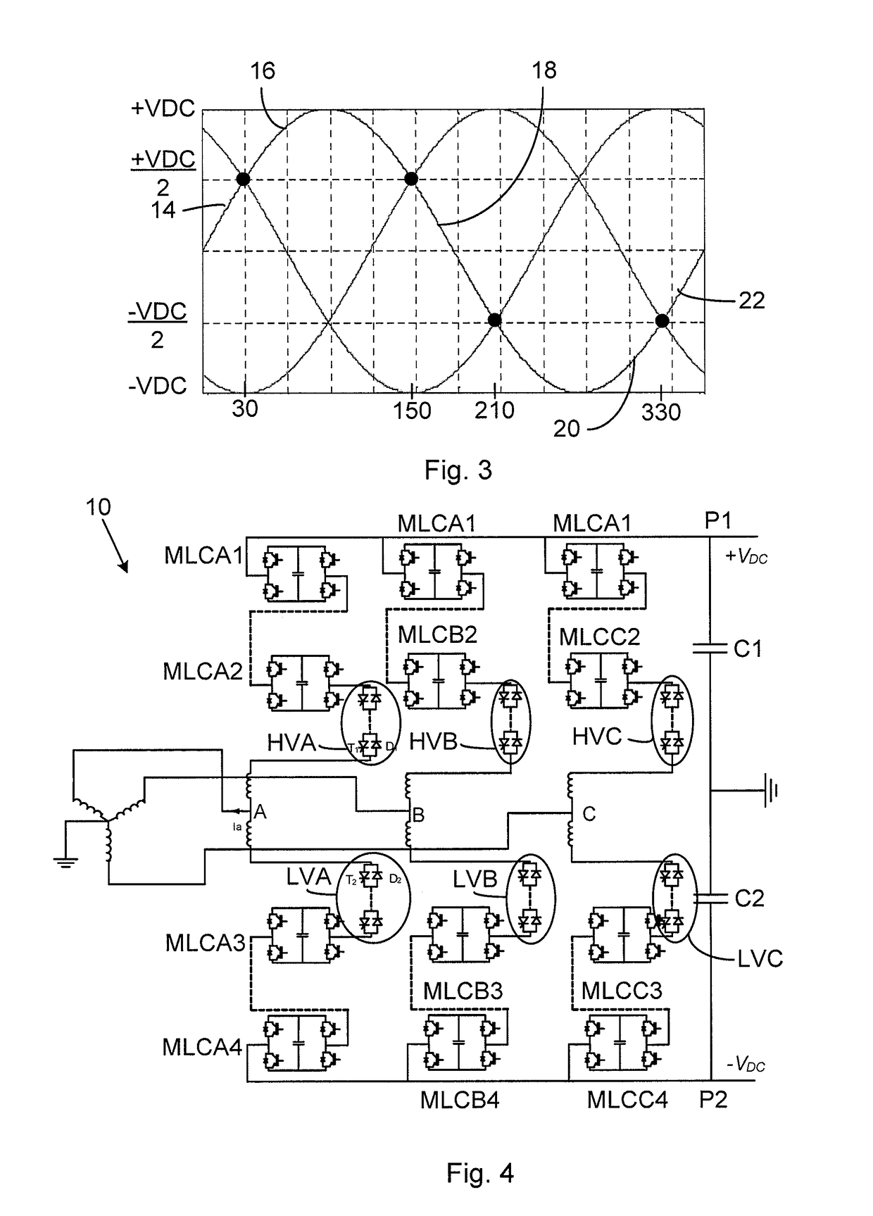
[0025]FIG. 1 shows a converter 10 according to a first embodiment of the invention. It comprises a three-phase bridge made up of a number of phase legs. There are in this case three phase legs. There is a first phase leg, a second phase leg and a third phase leg. The phase legs are more particularly connected between a first and a second direct current (DC) pole P1 and P2, where the first pole P1 provides a first voltage +VDC and the second pole P2 provides a second voltage −VDC. The mid points of the phase legs are each connected to a corresponding alternating current terminal TA, TB, TC. The midpoints are here connected to an alternating current (AC) terminal TA, TB and TC via a corresponding reactor Xr and the AC terminals are in turn connected to windings of a transformer TR, which windings in this case as an example are delta-connected.

[0026]The phase legs are in this first em...


PUM


Abstract

A voltage source converter includes a number of valves, the valves including switching elements with anti-parallel diodes provided in a bridge for switching between two states. The bridge is provided in at least one phase leg that stretches between two direct current poles and has at least one midpoint, which is connected to an alternating current terminal. The switching element of at least one valve is a thyristor. The converter further includes a commutation cell associated with the valve, where the commutation cell is controllable to reverse-bias the valve if it is to stop conducting current.

Description

FIELD OF INVENTION[0001]The present invention generally relates to voltage source converters. More particularly the present invention relates to a voltage source converter and a method of controlling the voltage source converter.BACKGROUND[0002]High Voltage Direct Current (HVDC) converters are mainly classified as Current Source Converters (CSC) and Voltage Source Converters (VSC). CSC converters are based on Line Commutated Converters (LCC) which contains thyristors. Thyristors have some inherent advantages such as being rugged, having low ON state losses, being easy to connect in series with each other, having a short time over-rating capability and having high power rating and being low cost. Moreover, thyristors are well evolved and commonly used components. However, LCC converters have a number of shortcomings: they may experience commutation failure, they require a strong alternating current (AC) grid, they do not support reactive power, have high harmonics, require polarity r...

Claims


Application Information

Patent Timeline
Patent Type & Authority Patents(United States)
IPC IPC(8): H02M7/487H02M5/443H02M7/483H02M7/48
CPCH02M5/443H02M7/487H02M2007/4811H02M2007/4835H02M7/4811H02M7/4835H02M1/0095
Inventor BARUPATI, PRAVEEN KUMARJONSSON, TOMASSUBRAMANIAN, SASITHARAN
Owner HITACHI ENERGY SWITZERLAND AG
Why Eureka
Try Eureka