Wastegate Valve

a wastegate valve and wastegate technology, applied in the field of wastegate valves, can solve the problems of increasing increasing the unit cost of the wastegate valve as well by a corresponding amount, and the valve to be expensive to produce, so as to reduce the cost of the wastegate valve, reduce the weight, and be more compact

Inactive Publication Date: 2021-01-21
NITTAN VALVE CO LTD
View PDF0 Cites 0 Cited by
  • Summary
  • Abstract
  • Description
  • Claims
  • Application Information

AI Technical Summary

Benefits of technology

[0050]As is clear from the foregoing description, because in at least some embodiments of the present invention a rotary shaft main body is secured to an attachment plate by means of solid-phase welding, this permits provision of a wastegate valve that may make it possible to achieve alleviation of constraints that would otherwise a...

Problems solved by technology

However, because the wastegate valve of such an embodiment would be exposed to high-temperature exhaust gas, it may be necessary or desirable that not only the valve body but also the rotary shaft, attachment plate, washer, and all of the other valve constituent members be made of heat-resistant alloy, the cost of which will increase as a function of the operating temperature limit of the alloy employed, thus causing increase in the unit cost of the valve as well by...

Method used


Image

  • Wastegate Valve
  • Wastegate Valve
  • Wastegate Valve

Examples


first embodiment

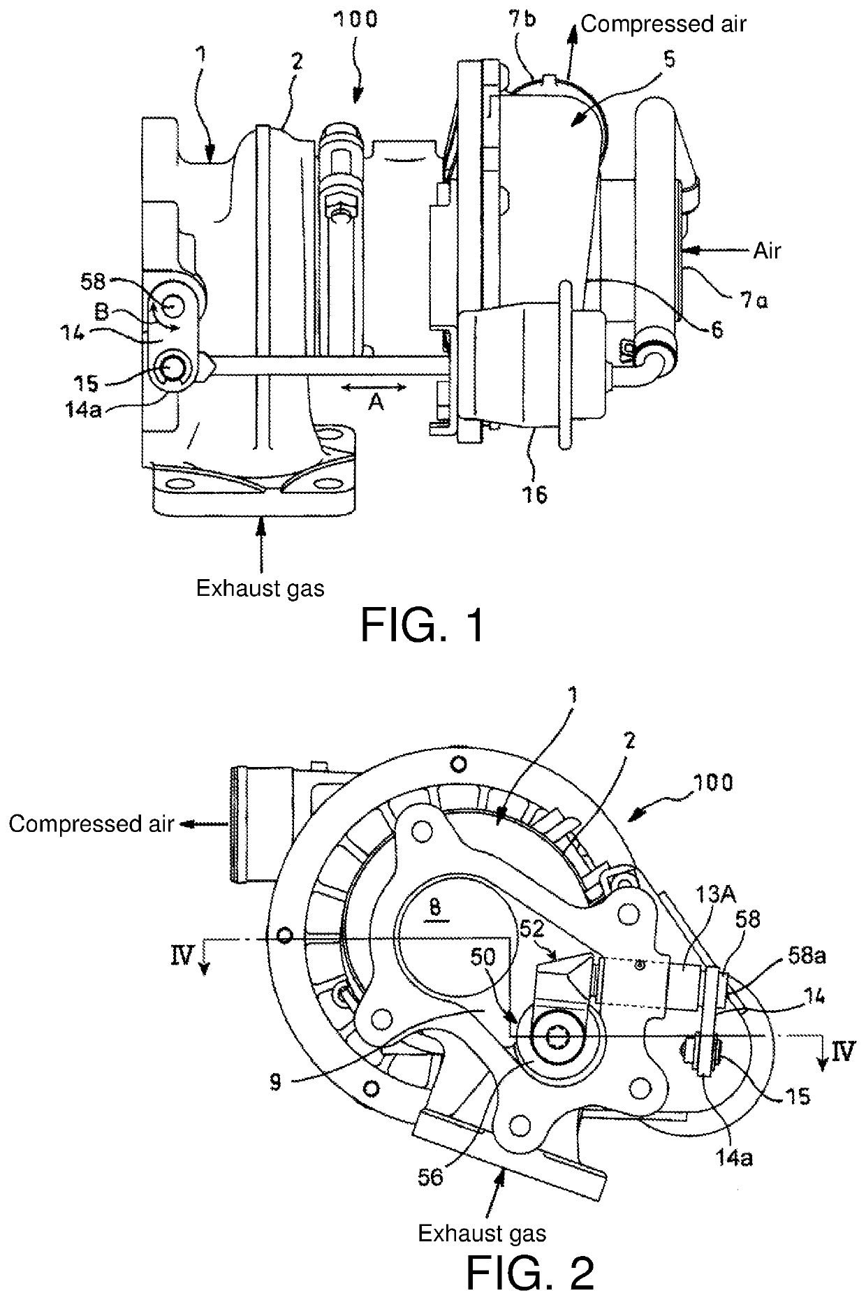
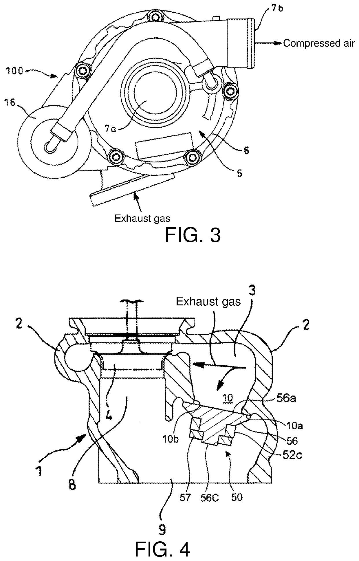
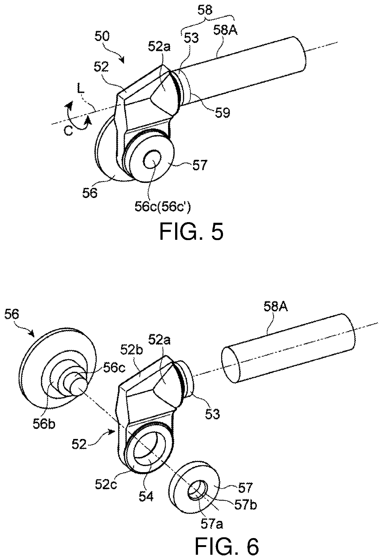
[0068]FIGS. 1 through 4 show a working example of an exhaust turbine turbocharger provided with a wastegate valve in accordance with a preferred embodiment of the present invention. More specifically, FIG. 1 is a side view of same exhaust turbine turbocharger, FIG. 2 is a front view of same exhaust turbine turbocharger, FIG. 3 is rear view of same exhaust turbine turbocharger, and FIG. 4 is a sectional view (sectional view along section IV-IV shown in FIG. 2) showing an exhaust gas flow path and a bypass flow path. Furthermore, FIGS. 5 through 10 are drawings showing wastegate valve 50 associated with a

[0069]At these drawings, reference numeral 1 is the turbine housing of exhaust turbine turbocharger 100, and within turbine housing 1 exhaust gas from the exhaust manifold of the engine is directed toward exhaust gas inlet 3 (see FIG. 4) of turbine scroll 2, exhaust gas supplied to turbine scroll 2 causing rotation of turbine impeller 4 (see FIG. 4).

[0070]Provided within compressor sc...

second embodiment

[0098]FIG. 12 shows a wastegate valve 50A associated with a second embodiment, this being shown as it would exist when installed at a turbine housing 1.

[0099]Rotary shaft 58 of wastegate valve 50A, i.e., rotary shaft 58 which extends from the side of attachment plate 52, is constituted from boss 53A which is formed in protruding fashion at the side of attachment plate 52, and rotary shaft main body 58B which is identical in diameter to boss 53A and which is joined by means of friction welding to boss 53A. Stating this another way, boss 53A which is formed in protruding fashion at the side of attachment plate 52, and rotary shaft main body 58B which is joined to boss 53A, cooperate to constitute rotary shaft 58 which bears on bearing 13A provided at turbine housing 1. Note that the length L1 by which boss 53A protrudes is greater than that of boss 53 formed at attachment plate 52 of wastegate valve 50 at the foregoing first embodiment.

[0100]Furthermore, while valve body 56 and attach...

third embodiment

[0103]FIG. 13 shows a wastegate valve 50B associated with a third embodiment, this being shown as it would exist when installed at a turbine housing 1.

[0104]Rotary shaft 58 of wastegate valve 50B is constituted from boss 53 which is formed in protruding fashion at the side of attachment plate 52 constituted from the high-Ni alloy NCF751 (operating temperature limit 950° C.), and rotary shaft main body 58C which is in the shape of a hollow pipe, which is constituted from stainless steel (operating temperature limit 850° C.), and which is joined (secured) by means of friction welding to boss 53.

[0105]In addition, rotary shaft 58 bears on bearing 13A provided at turbine housing 1, and the hollow portion of rotary shaft main body 58C which makes up rotary shaft 58 extends all the way through turbine housing 1 in such fashion as to be open to the exterior of turbine housing 1.

[0106]Because rotary shaft main body 58C is hollow and lightweight, the overall weight of wastegate valve 50B wil...


PUM


Abstract

A wastegate valve may be formed such that the overall shape thereof is approximately L-shaped as seen in plan view and such that a rotary shaft extends, in a direction approximately perpendicular to a central axis of a valve body and in such fashion as to be offset from the valve body, from an attachment plate which supports the valve body. Furthermore, a rotary shaft main body may be secured by solid-phase welding to a side of the attachment plate. By making the attachment plate more compact, reduction in overall weight, decrease in valve cost, and/or alleviation of constraints that would otherwise apply to design of an exhaust gas flow path provided with a bypass flow path may be achieved.

Description

CROSS-REFERENCE TO RELATED APPLICATION, BENEFIT CLAIM, AND INCORPORATION BY REFERENCE[0001]This application is a continuation-in-part of and claims benefit under 35 USC 120 and 365(c) to copending International Application No. PCT / JP2018 / 014596, entitled “Wastegate Valve”, filed 5 Apr. 2018, the content of which is incorporated herein in its entirety by reference.FIELD OF THE INVENTION[0002]The present invention pertains to a wastegate valve that is provided at an exhaust gas flow path in an engine which is turbocharged through use of a turbocharger and that adjusts the amount of exhaust gas which flows into a turbine by causing diversion of a portion of the exhaust gas, and in particular relates to a wastegate valve which is formed such that the overall shape thereof is approximately L-shaped as seen in plan view and in which a rotary shaft extends, in a direction approximately perpendicular to the central axis of a valve body and in such fashion as to be offset from the valve body...

Claims


Application Information

Patent Timeline
IPC IPC(8): F02B37/18F16K1/20
CPCF02B37/186F16K1/2007Y02T10/12F02B37/183F05D2230/239F01D17/105F05D2260/606F01D17/145F05D2230/21F05D2230/25
Inventor MIKAMI, MAIKU
Owner NITTAN VALVE CO LTD
Why Eureka
Try Eureka